
Systems and methods for placing a braided, tubular sleeve in a well bore

a tubular sleeve and well bore technology, applied in the direction of braid, wellbore/well accessories, mechanical equipment, etc., can solve the problems of sleeve damage, sleeve cannot be hardened as desired, etc., and achieve the effect of minimizing particulate flow, easy optimization, and high hardness

Inactive Publication Date: 2006-08-01
HALLIBURTON ENERGY SERVICES INC
View PDF78 Cites 23 Cited by
  • Summary
  • Abstract
  • Description
  • Claims
  • Application Information

AI Technical Summary

Benefits of technology

[0029]In still another embodiment, implementations of the invention may include applications external to metallic casing or sand screens. In one such application, shown in FIG. 7, the casing comprises a metallic expandable tubular 146, used in well construction for reducing or eliminating diameter transitions, such as in a monobore well. In this application, the sleeve may be run into the well prior to placement of the metallic casing or can be inserted into the well on the outer diameter of the metallic casing. In order to maintain a continuous sleeve, a longitudinal or helical seam may be required that is either stitched or adhered together during installation. The tubular braided sleeve 148 expands as the casing or screen is expanded by the drawing of a mandrel 142 which is pulled toward the surface using a cable or wireline 144. This configuration is particularly useful in combination with embedded metallic conductors or optical fiber for use in conductors because of the difficulty in providing for signal and data communication in monobore or reduced diameter transition wells. Because the structural support provided by the tubular braided sleeve may reduce the forces and stresses on the metallic expandable casing, one advantage of the present invention is to reduce the weight and thickness requirement for the metallic expandable casing or screen thereby decreasing the forces and pressure required to expand the metallic expandable casing or screen as well as the time required to accomplish that expansion. These factors may also allow for a larger diameter change during expansion of the metallic expandable casing or screen. The heat required for curing can be provided by circulating high temperature fluids within the bore of the tubular, by electrical resistance heating of conductors embedded in the composite braid, by an exothermic reaction of casing cement in the vicinity of the sleeve, or by any other practical means.
[0030]In another embodiment of the invention, for use as production tubing or casing in deep wells, an internal cable (not shown) is placed within the tubular braid in order to support the tension loading during installation. The internal cable may be metallic, high performance polymer, or other material capable of bearing high longitudinal tensile stress. The internal cable is preferably incorporated into the braid to distribute the load due to the weight of the sleeve to the cable and may optionally also support the weight of a device at the bottom of the sleeve, such as a bottom hole assembly. Similarly, a longitudinal cable may be utilized to support the tubular braided sleeve during installation. Such a cable may be external or internal to the sleeve and may be removed after installation and curing of the resin.
[0031]Another use for the present invention is as a means for installing and fixing in place a composite screen for the purposes of particulate control, more specifically for confining sand to the formation while allowing the production fluid to flow out of the formation into the well bore. Current sand screens are manufactured as multiple layers of corrosion resistant steel expanded metal and wire screens. A composite braided sleeve, or multiple braided sleeves, can be employed as a sand screen. A tubular braided sleeve can also be used as a protective shroud or layer over conventional metallic screens. The composite braided tubular sleeve could also incorporate metallic and / or fiber optic conductors and / or sensors into the fabric to make a smart sand screen.
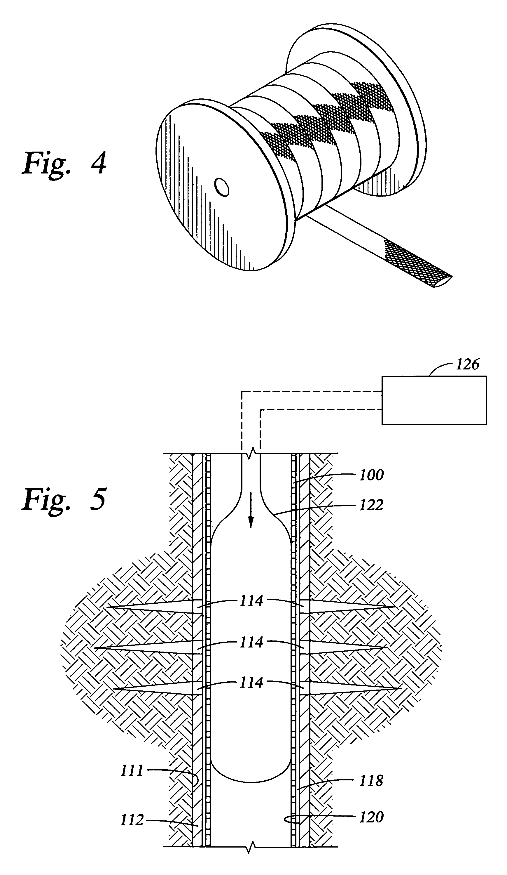
[0032]The braiding configuration can be easily optimized for the necessary mesh size as required to minimize particulate flow into the well bore. It may also be possible to provide an adjustable mesh size by axially compressing or expanding the mesh to change the mesh size to allow for screen cleaning by backflushing the screen. The braided sleeve impregnated with a resin can be used as a means for providing a composite screen that can be inflated either mechanically or hydraulically (using a bladder inside to expand). Once the sleeve is in contact with the formation face and allowed to set, it would act as a sand control device that conforms to the well bore.
[0033]During drilling operations, a patch of braided sleeve can be used to cover a water-producing zone or a low fracture gradient zone or can be placed within a horizontal well bore to stabilize the well bore against collapse. The braided sleeve can be placed around the drill string and expanded at the pre-specified location.
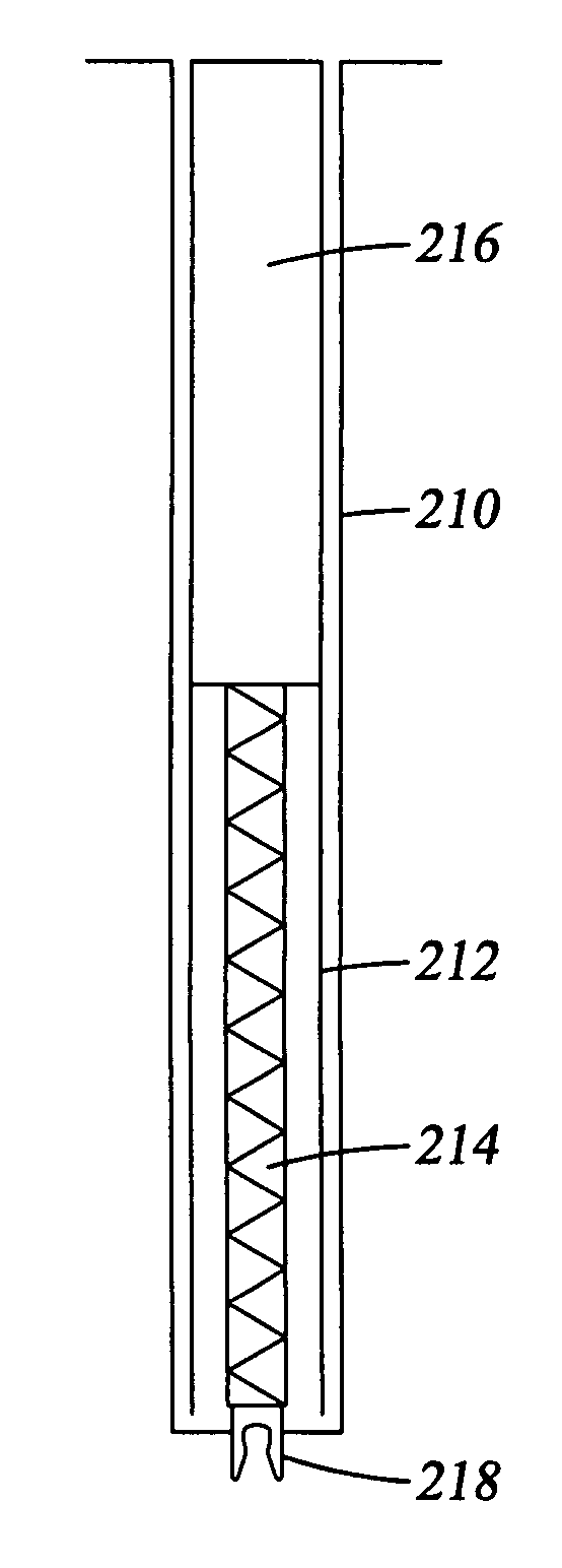
[0034]In yet another embodiment, the previously described tubular, braided sleeve may be easily installed in a well bore using systems that include a carrier (or sub) configured to hold the sleeve. FIG. 8 depicts such a system being used to place a braided sleeve 214 in a well bore 210. The sleeve 214 is disposed within an interior of a carrier 212, which surrounds the length of sleeve 214. Further, an upper end of carrier 212 is attached to a lower end of a conveyance string 216, e.g., a drillpipe or tubing, for lowering carrier 212 into well bore 210. Alternatively, carrier 212 may be attached to other types of conveyance strings, e.g., a wireline 211 as shown in FIG. 12, to lower it downhole. In addition, an anchor 218 may be detachably attached with, e.g., shear pins, to the base of sleeve 214 for securing the sleeve to the bottom of well bore 210. Alternatively, extending arms attached to the base of sleeve 214 can be utilized to anchor sleeve 214 to the formation wall (not shown). The extending arms are similar to those currently used on caliber tools. The extending arms may be maneuvered to drive the anchors into the sidewall of the formation, allowing sleeve 214 to be positioned mid-way in well bore 210. Although not shown, the system may also include an inflatable member inside of sleeve 214 for expanding a diameter of sleeve 214 when desired.

Problems solved by technology

Unfortunately, fluids flowing in the well bore, e.g., drilling fluid, can undesirably wash away this resin such that the sleeve cannot be hardened as desired.
Another problem that may be encountered when installing the sleeve is that the sleeve may become damaged by the rough edges of the rock that forms, along the wall of the well bore drilling.

Method used


Image

  • Systems and methods for placing a braided, tubular sleeve in a well bore
  • Systems and methods for placing a braided, tubular sleeve in a well bore
  • Systems and methods for placing a braided, tubular sleeve in a well bore

Examples


example 1

[0047]Several samples of a 3″ long and 1″ diameter fiber glass biaxial tubular fabric obtained from A&P Technology of Cincinnati, Ohio was soaked in a variety of solutions for 3 to 5 minutes as shown in Table 1. All the solutions were made by adding the amounts indicated in Table 1 to a 0.70 milliliter (ml) solution of FWCA hydroxyethylcellulose (HEC) available from Halliburton Co. The viscosity of each solution was 710 centipoise (# 1 Spindle @ 6 revolutions per minute) using a Brookfield viscometer.

[0048]After soaking, each sample was allowed to drain in a beaker in open air. As presented in Table 1, the flexibility of the fibers and the coverage of open network in the braided fabric of each sample were judged relative to each other. The most desirable solution formulations were determined to be the ones that covered the tubular fabric in a thick and homogeneous manner during the treatment stage and left a good film over the entire fabric while retaining the flexibility of the fab...

example 2

[0050]The treated, dried glass fiber tubular samples 8 and 9 were heated at 160° F. in a 10 weight % ammonium chloride solution for 24 hours to achieve curing of the melamine resin present in the formulation. The samples were taken out and examined for enhanced stiffness of the fabric. While both tubular samples exhibited increased stiffness, sample 8 was slightly stiffer than sample 9.


PUM


Abstract

Systems and methods for placing a tubular, braided sleeve in a well bore. The sleeve is positioned within an interior of a carrier configured to hold the sleeve in an undeployed position, followed by lowering the carrier into the well bore. The sleeve may be used in conjunction with a curable resin that can be solidified to set the sleeve into a tubular cross section. After securing the sleeve to the well bore, the carrier may be moved away from the bottom of the well bore, deploying the sleeve and extending it along the contour of the well bore. The tubular sleeve may then be subsequently expanded in situ to increase its diameter. The curable resin can then cured to make the sleeve substantially rigid.

Description

CROSS-REFERENCE TO RELATED APPLICATIONS[0001]The subject matter of the present application is related to U.S. patent application Ser. No. 10 / 352,809, filed Jan. 28, 2003, now abandoned, and entitled “Post Installation Cured Braided Continuous Composite Tubular”, incorporated by reference herein in its entirety.FIELD OF THE INVENTION[0002]The present invention generally relates to drilling wells that penetrate subterranean formations. More specifically, the invention relates to systems and methods for using a carrier to place a braided, tubular sleeve in a well bore.BACKGROUND OF THE INVENTION[0003]Natural resources such as gas, oil, and water residing in a subterranean formation can be recovered by drilling well bores through the formation. As described in U.S. patent application Ser. No. 10 / 352,809, a braided, tubular sleeve can be placed in a well bore for various purposes such as sealing and maintaining the integrity of the well bore and for conveying devices having the ability t...

Claims


Application Information

Patent Timeline
Patent Type & Authority Patents(United States)
IPC IPC(8): E21B29/00E21B17/02F16L11/02D04C1/06E21B23/00E21B29/10E21B43/10
CPCD04C1/06E21B23/00E21B43/108E21B43/103E21B29/10
Inventor ZAMORA, FRANKREDDY, B. RAGHAVAKALMAN, MARK D.
Owner HALLIBURTON ENERGY SERVICES INC
Learn More