
Low-volume ice making machine

a low-volume, ice-making machine technology, applied in the field of ice-making machines, can solve the problems of large space occupation, less desirable clouded ice, and large volume of conventional ice-making machines, and achieve the effect of not producing large cubes of clear ice on the ice machin

Inactive Publication Date: 2006-08-01
PENTAIR FLOW SERVICES
View PDF27 Cites 60 Cited by
  • Summary
  • Abstract
  • Description
  • Claims
  • Application Information

AI Technical Summary

Benefits of technology

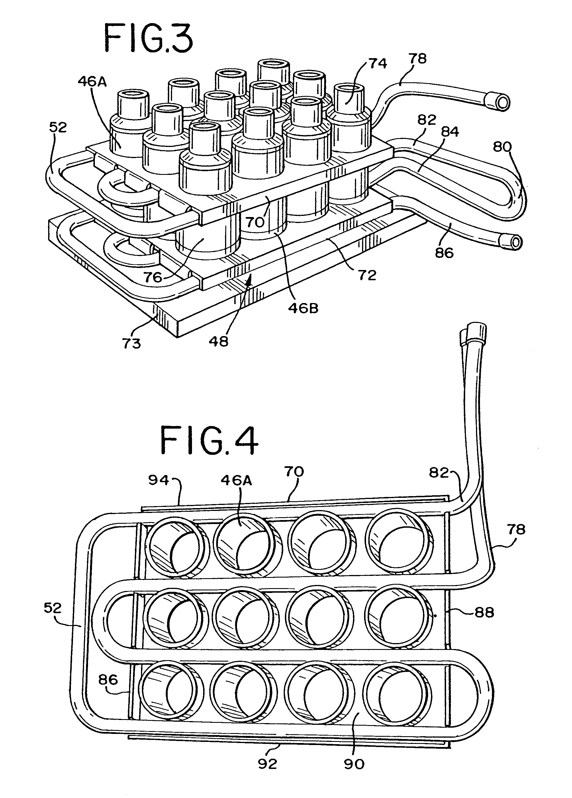
[0091]Thus, it is apparent that there has been described, in accordance with the invention, a low volume ice making machine that fully provides the advantages set forth above. The preferred ice machine of the invention produces large, individual, clear ice cubes that can be handled by tongs and, accordingly, are desirable for residential use. The ice machine can be easily manufactured from inexpensive, injection molded plastic parts that can be formed to snap together. The metal parts of the evaporator can be easily made by an automated metal stamping and forming process. The evaporator design offers high reliability and requires infrequent maintenance. Further, the stacking feature of the evaporator design permits the ice capacity to be increased without increasing the foot-print of the ice machine.

Problems solved by technology

Most domestic ice makers found in refrigerators freeze standing water, which produces clouded ice that is less desirable.
In addition to producing small ice cubes, conventional ice making machines are typically large and bulky machines that require a large amount of space.
Typically, such ice machines do not produce large cubes of clear ice.
One model produces large, clear cubes, but uses an evaporator that is fairly difficult to produce.
Also, the evaporator is not totally reliable and uses spray jets that have a tendency to get plugged up, especially when routine maintenance is not carried out.
Nonexistent or, at best, infrequent maintenance is typical for residential ice machines.

Method used


Image

  • Low-volume ice making machine
  • Low-volume ice making machine
  • Low-volume ice making machine

Examples


Embodiment Construction

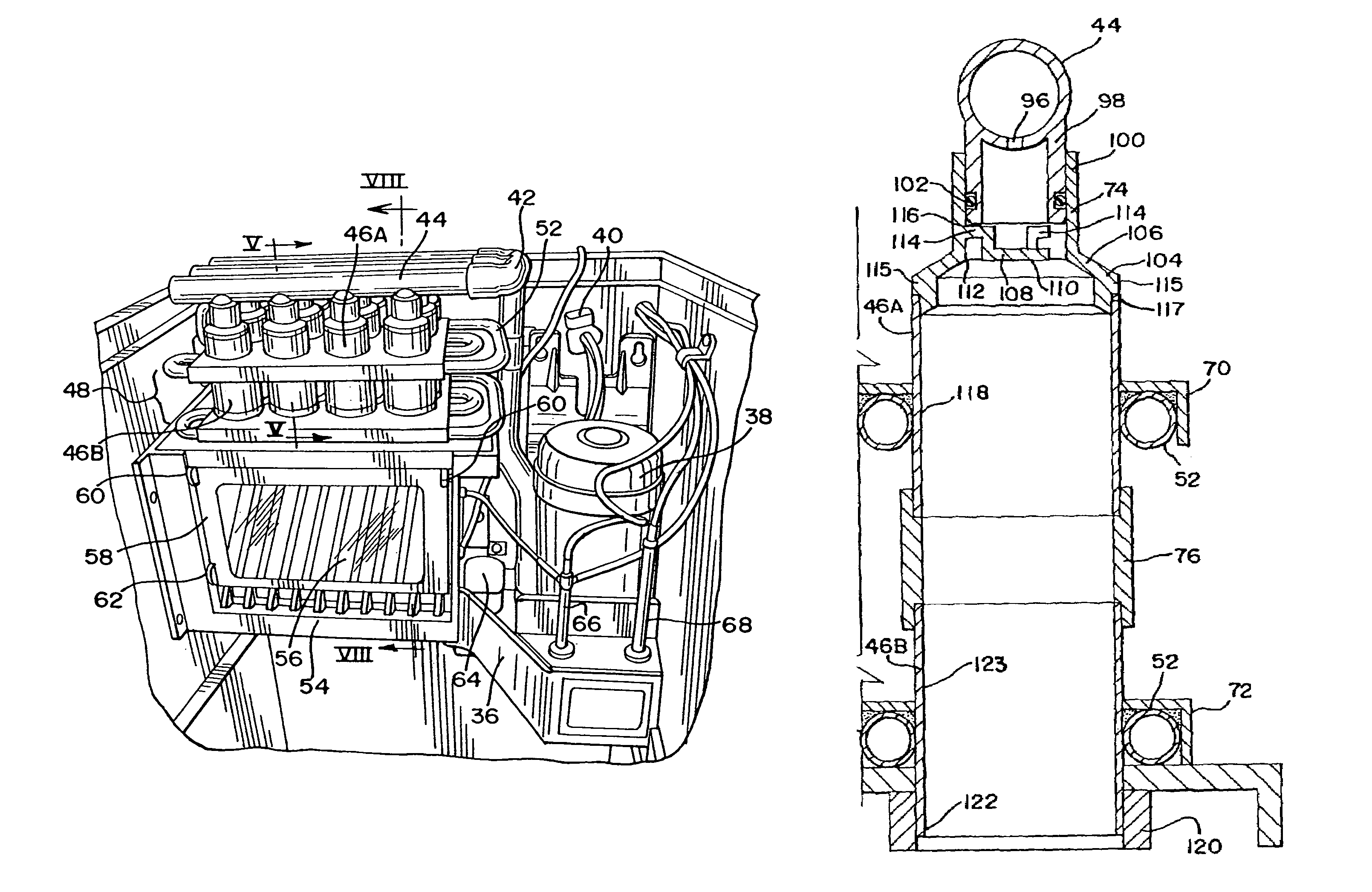
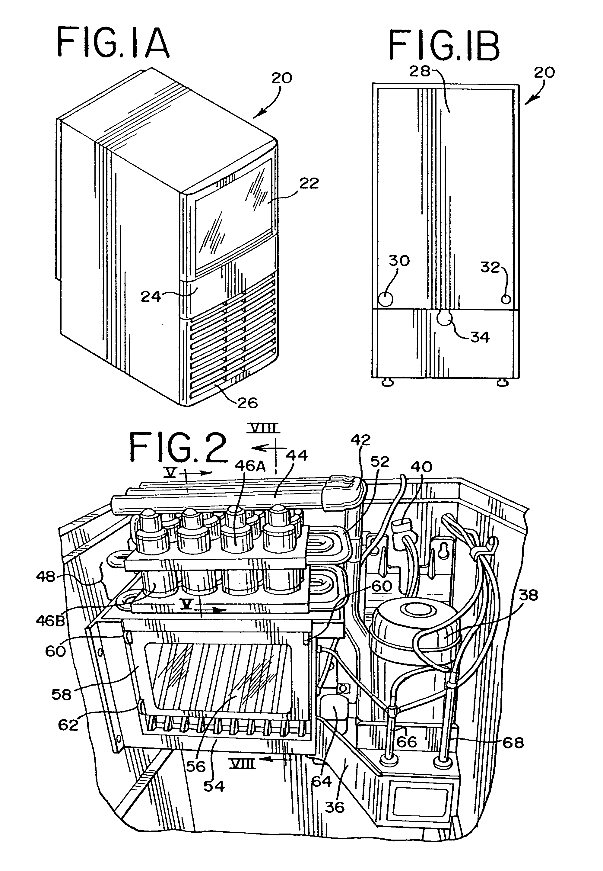
[0031]In accordance with a preferred embodiment the invention, an ice machine is provided that produces large, individual, clear ice cubes, and is contained within a compact-sized cabinet suitable for use in either residential or commercial settings. One embodiment of a cabinet suitable for housing the ice machine of the invention is illustrated in FIGS. 1A and 1B. Cabinet 20 is configured to stand upright on a horizontal surface and has a somewhat narrow profile to facilitate positioning cabinet 20 in small spaces found within a residential kitchen or small commercial kitchen. In one embodiment of the invention, cabinet 20 has a height of no more than about thirty inches, a depth of no more than about twenty three inches and a width of no more than about fifteen inches.

[0032]Ice cubes can be accessed from an ice storage bin (not shown) through a door 22 on a front face 24. Front face 24 also includes a cooling vent 26 that permits the flow of air to the refrigeration system of the ...


PUM


Abstract

An ice machine includes an evaporator with a plurality of individual ice-forming cells. Each ice-forming cell is open at a lower end. A water distributor is coupled to the evaporator and configured to deliver water to the upper end of each ice-forming cell. A refrigeration system in the ice machine is configured to cool each of the plurality of ice-forming cells, such that individual ice cubes are formed in each ice-forming cell. A water recirculation system includes a water collection unit positioned between the evaporator and a water sump. The water collection unit collects water flowing from the ice-forming cells in first and second chambers. A water detection probe is positioned in the second chamber. A harvest cycle is initiated when the water level in the second chamber falls below a specified level. A method of operating the ice machine is also provided.

Description

RELATED APPLICATIONS[0001]The present patent document claims priority to Provisional Application Ser. No. 60 / 498,765, filed Aug. 29, 2003, which is hereby incorporated by reference.FIELD OF THE INVENTION[0002]The present invention relates, in general, to ice making machines and, more particularly, to low-volume ice making machines suitable for residential or commercial use.BACKGROUND[0003]Ice making machines are in widespread use for supplying cube ice in commercial operations. Typically, the ice making machines produce a large quantity of ice by flowing water over a large chilled surface. The chilled surface is thermally coupled to evaporator coils that are, in turn, coupled to a refrigeration system. The chilled plate, or evaporator, contains a large number of indentations on its surface where water flowing over the surface can collect. Typically, the indentations are die-formed recesses within a metal plate having high thermal conductivity. As water flows over the indentations, i...

Claims


Application Information

Patent Timeline
Patent Type & Authority Patents(United States)
IPC IPC(8): F25C1/06F25C1/22
CPCF25C1/06F25C1/225F25C2700/04F25C2600/04F25C2400/12F25C1/25
Inventor SCHLOSSER, CHARLES E.MILLER, RICHARD T.SHEDIVY, SCOTT J.
Owner PENTAIR FLOW SERVICES
Learn More