
X-ray anode having an electron incident surface scored by microslits

a microslit and electron incident surface technology, applied in the field of x-ray anodes, can solve the problems of material flow events, material volume missing, orange peel-like corrugation of the surface, etc., and achieve the effect of roughening the surfa

Inactive Publication Date: 2006-07-18
SIEMENS HEALTHCARE GMBH
View PDF13 Cites 34 Cited by
  • Summary
  • Abstract
  • Description
  • Claims
  • Application Information

AI Technical Summary

Benefits of technology

[0009]An object of the present invention to provide an x-ray anode with a highly thermally stressable surface, as well as a method to produce such an x-ray anode, in which the probability of the formation of thermal stress tears, as well as a roughening of the surface due to the thermal load, is largely prevented or at least reduced to a significant degree.
[0012]By the introduction of defined microslits in the surface, material volumes exposed to thermal stresses are freed from mutual expansion constraints, such that microscopic volumes located between the microslits can move freely and can expand laterally in all directions without colliding with an adjacent volume element. Therefore, the material deformation remains elastic approximately to its original condition, meaning the macroscopic volume elements can expand and contract again upon cooling, without a remaining material deformation ensuing. Substantial plastic expansions and compressions and, as a consequence thereof, material wear are prevented. Consequently, the formation of cracks and the roughening of the surface are significantly prevented.

Problems solved by technology

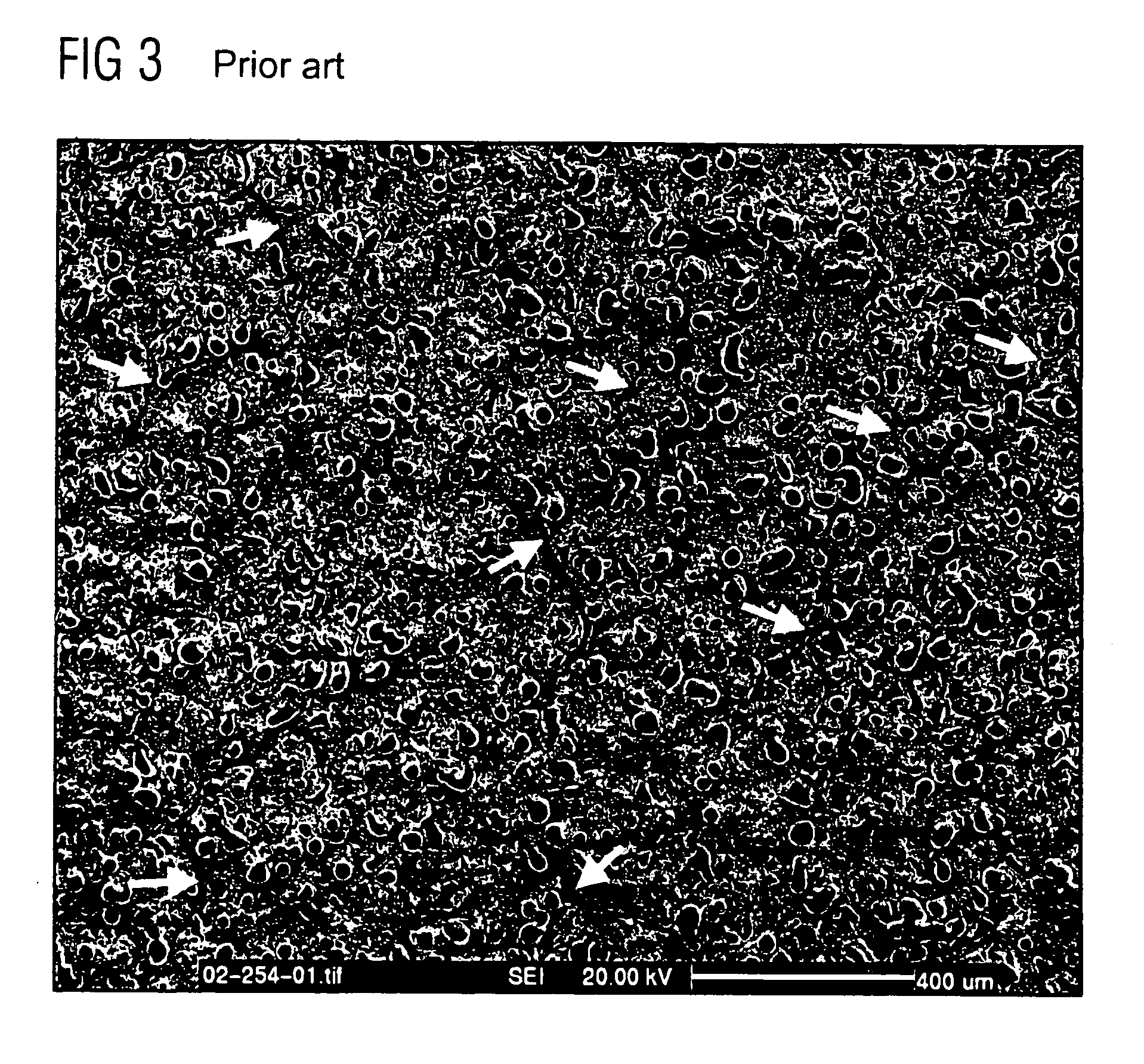
This material flow to the surface is initially relatively imperceptible however, given a larger number of thermal stress cycles, this accumulates, to that it can lead to a corrugation of the surface that resembles an orange peel.
Furthermore, due to the macroscopic expansion constraint, it leads to flow events within the material, such that the substance in the material itself is plastically compressed, even when macroscopically the dimensions of the volume element remain the same in the sideways length.
Since a portion has flowed away upwardly, however, this material volume is missing, and given frequent repetition of the effect it leads to tear formations in the surface.

Method used


Image

  • X-ray anode having an electron incident surface scored by microslits
  • X-ray anode having an electron incident surface scored by microslits
  • X-ray anode having an electron incident surface scored by microslits

Examples


Embodiment Construction

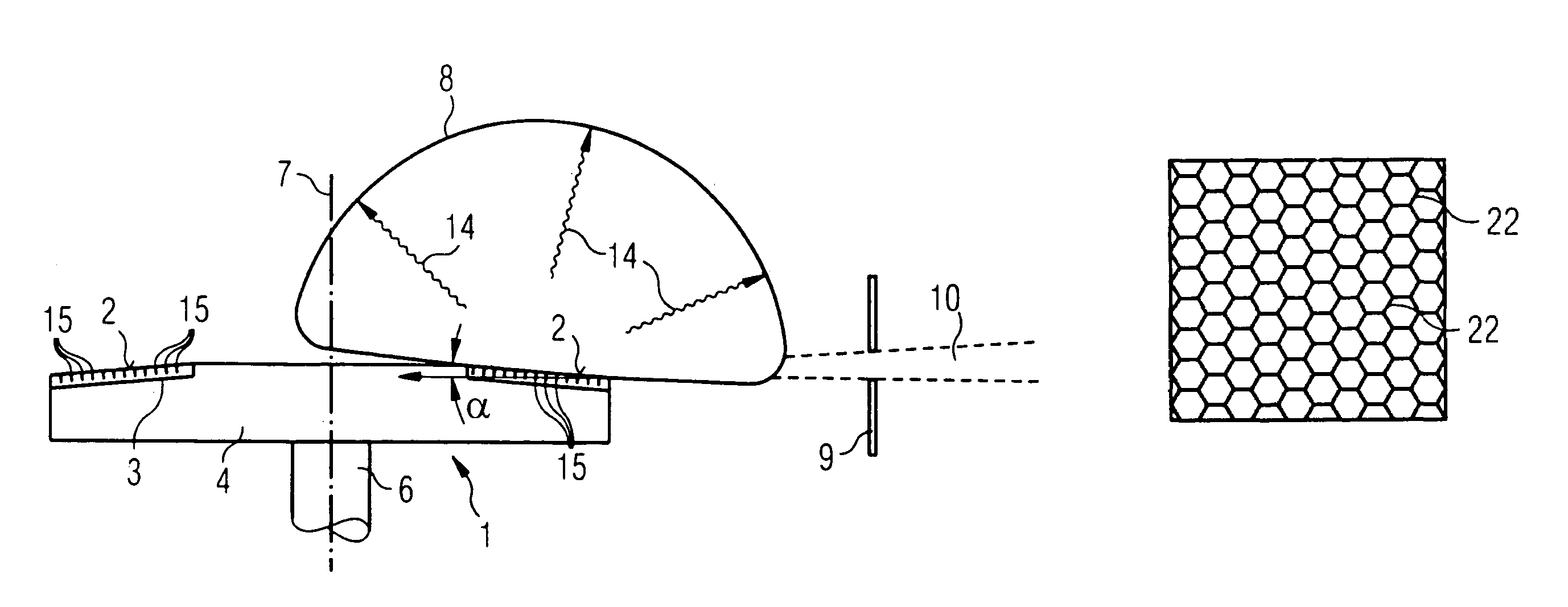
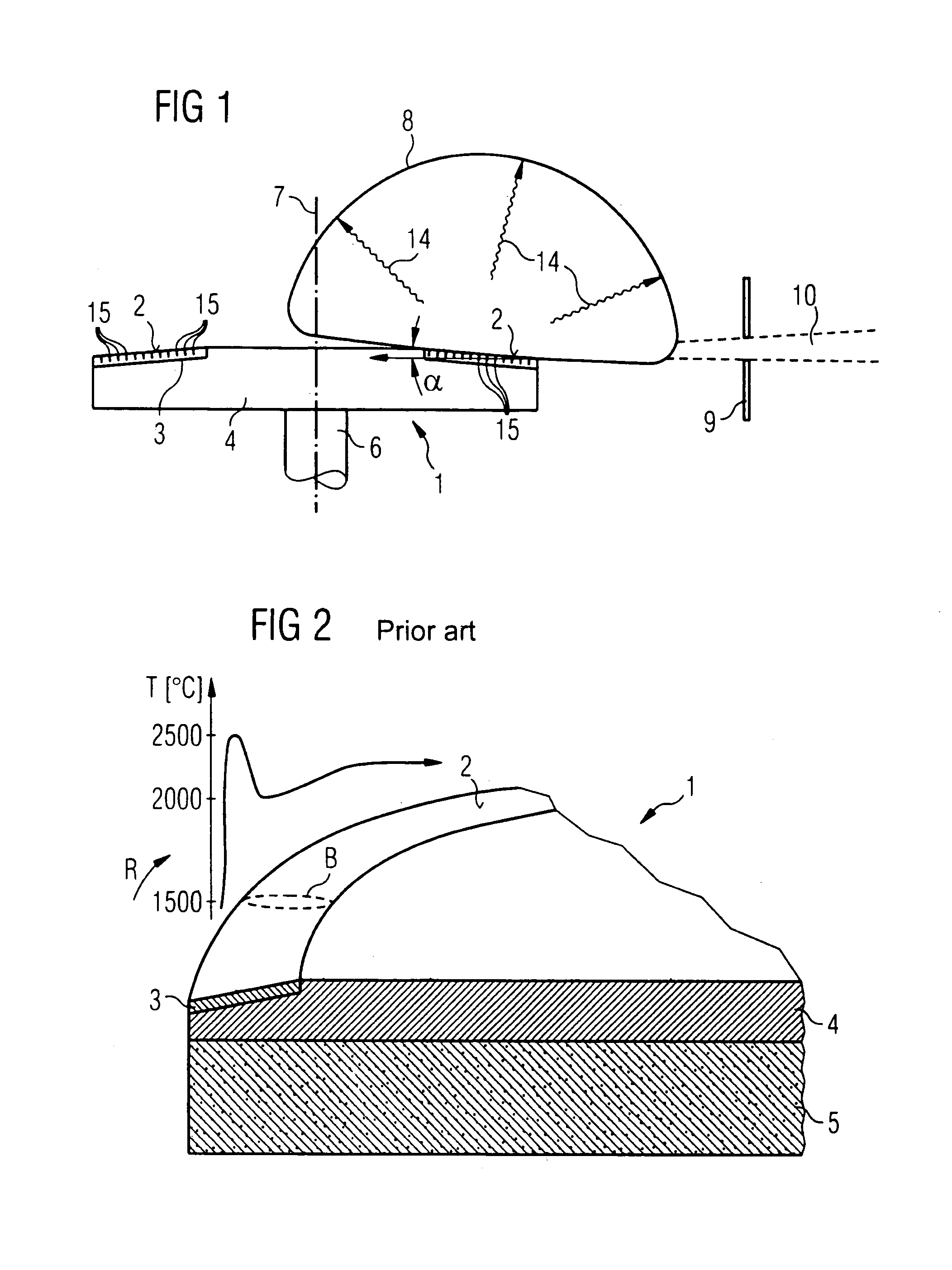
[0046]In the description below, it is assumed, insofar as it is not noted otherwise, that the x-ray anode 1 is a rotating anode 1 having a focal path surface 2 in which microslits are introduced. FIGS. 1 and 2 show the principle assembly of such a rotating anode 1.

[0047]The rotating anode 1 is a substantially planar, circular anode plate 4 made from molybdenum or TZM. A material layer 3 made of tungsten, with a proportion or approximately 5% rhenium (WRe 5) is located along the outer circumference. The surface 2 of this layer 3 is the focal path surface that, as was already described above in connection with FIG. 2, is exposed to strongly varying thermal stresses. The anode plate 4 is attached to a shaft 6, via which the anode plate 5 is displaced in rotation around the axis of symmetry 7 lying perpendicular to the plate surface. The focal spot B, at which the accelerated, high-energy electrons strike on the focal path surface 2, thereby moves around the focal path surface 2. By int...


PUM

PropertyMeasurementUnit
Lengthaaaaaaaaaa
Lengthaaaaaaaaaa
Lengthaaaaaaaaaa

Abstract

An X-ray anode is produced by scoring at least a region of a surface of the anode, on which electrons are incident, with a number of defined microslits, thereby making the surface, or at least the region thereof, highly thermally stressable.

Description

BACKGROUND OF THE INVENTION[0001]1. Field of the Invention[0002]The present invention concerns an x-ray anode with a highly thermally stressable surface, as well as a method to produce such an x-ray anode.[0003]2. Description of the Prior Art[0004]X-ray anodes in conventional x-ray tubes have a surface that, due to its intended purpose, is exposed to a significant thermal stress that varies over a large range. To generate the x-ray radiation, the surface of such an x-ray anode is struck by a beam of high-energy electrons. Upon deceleration of the electrons in the surface of the x-ray anode, the desired x-ray radiation results. At the point on the surface of the x-ray anode on which the electron beam strikes, known as the focal spot, temperatures of up to 2500° C. occur. In order to increase the lifespan of the x-ray tubes, in many cases rotating anode tubes are used in which a plate-like x-ray anode rotates around its axis of symmetry. The electron beam strikes this rotating anode i...

Claims


Application Information

Patent Timeline
IPC IPC(8): H01J35/10B23K26/14B23K26/36B23K26/42H01J9/02H01J35/08
CPCB23H7/108B23K26/367H01J35/08B24C1/045H01J9/02B23K26/421B23K26/364B23K26/60H01J35/105
Inventor LENZ, EBERHARD
Owner SIEMENS HEALTHCARE GMBH
Learn More