Dual-frequency microwave sensor

Inactive Publication Date: 2006-07-18
OPTEX CO LTD
View PDF11 Cites 18 Cited by
  • Summary
  • Abstract
  • Description
  • Claims
  • Application Information

AI Technical Summary

Benefits of technology

[0007]The present invention has been devised in consideration of these issues. Therefore, an object of the present invention is to provide a MW sensor that, with respect to MW sensors that use two frequencies of microwaves to detect an object, can accurately discriminate the distance to the object and avoid false alarms.
[0008]In order to achieve the above object, the present invention is configured so that it can accurately discriminate the distance to the detected object by also detecting the signal level of reflected waves and by using the phase difference of the reflected waves and the signal level of the reflected waves in order to overcome the influence of the above-described fold-over error when measuring the distance to an object based on the microwaves (reflected waves) reflected by the object.
[0012]With these specified items, even when two points are obtained as the distance to the object that is obtained by using the phase difference of the respective reflected waves due to fold-over error, it is possible to easily judge which of the two points is the correct distance to the object by detecting the signal level of the reflected waves from the object. For example, when the present sensor is applied as a crime prevention sensor, it is possible to easily judge whether the detected object is present inside the area that is intended to be protected or the detected object is present outside the area that is intended to be protected. In this way, it is possible to avoid false alarms and to thus achieve improved sensor reliability. FIG. 3 shows an example of the relationship between the distance to an object outdoors and the signal level of the reflected waves. As shown in FIG. 3, the signal level voltage is theoretically inversely proportional to the square of the distance to the object. For example, the signal level voltages for a distance of 5 m to the object and a distance of 25 m to the object differ by a factor of twenty or greater. By using such a phenomenon, the present invention is able to also detect the signal level of waves reflected from an object and thereby accurately measure the distance to the object.

Problems solved by technology

However, this type of sensor has the following issues due to the fact that the distance to the target is obtained by using only the phase difference of two IF signals. FIG. 5 shows the relationship between the absolute value of the phase difference (hereafter, simply called “phase difference”) of the two IF signals of this type of sensor and the distance to the target.
That is, there is no unique relationship between the phase difference of the IF signals and the distance to the target that is obtained by using that difference, and therefore, it is impossible to accurately obtain the distance to the target by using only the IF signal phase difference.

Method used


Image

  • Dual-frequency microwave sensor
  • Dual-frequency microwave sensor
  • Dual-frequency microwave sensor

Examples


Embodiment Construction

[0018]Hereinafter, embodiments of the present invention are described with reference to the appended drawings. A description is given here in regard to the case of using a MW sensor as a crime prevention sensor, in which the present invention is applied to a MW sensor that has been made capable of measuring the distance to an object to be detected (an intruder or the like) by using microwaves with two different frequencies.

Description of the Configuration of the MW Sensor

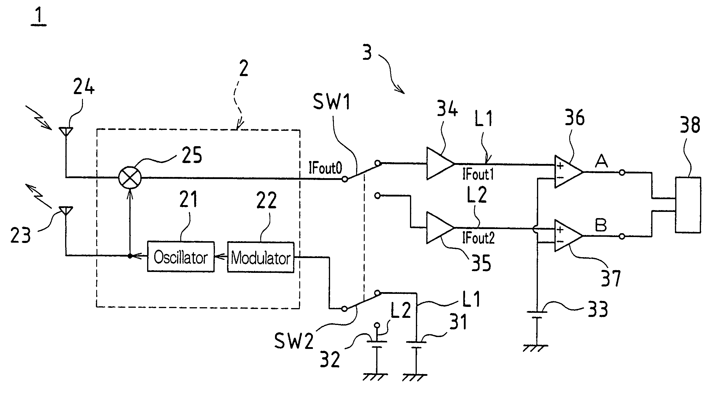
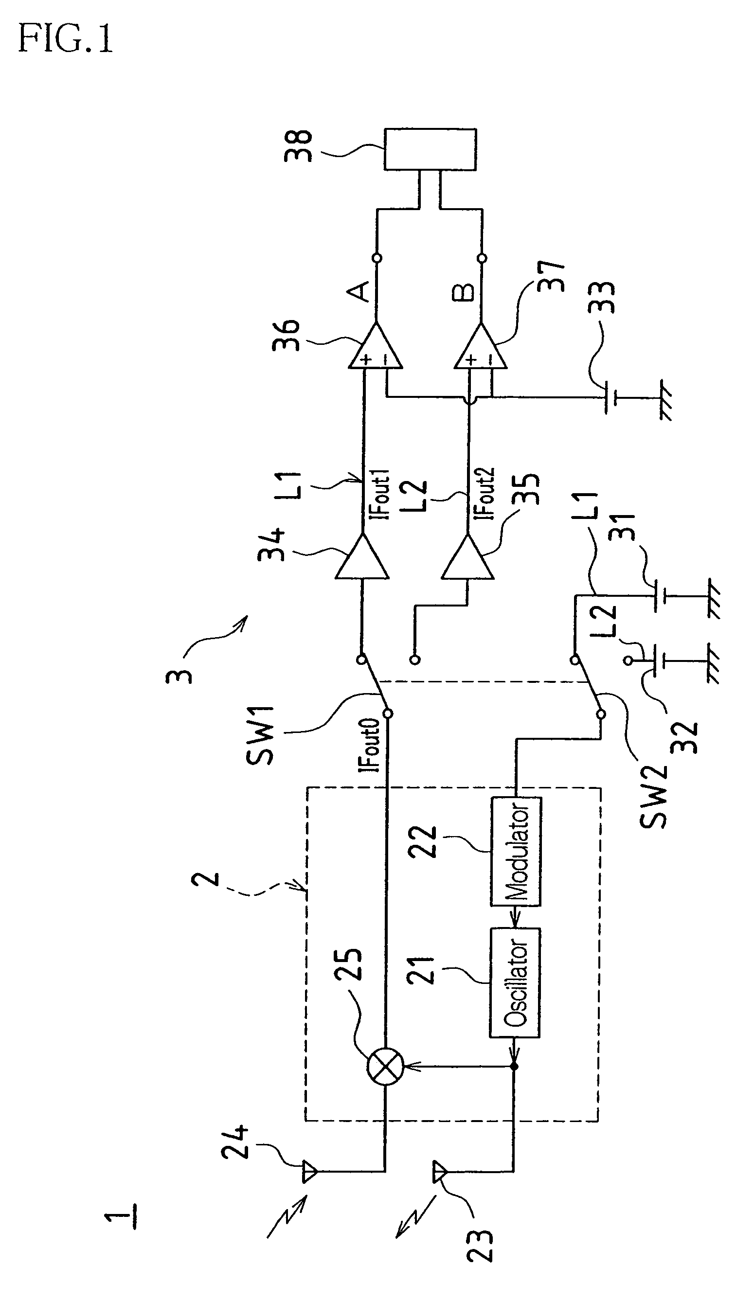
[0019]FIG. 1 shows a circuit configuration of a MW sensor 1 according to this embodiment. As shown in FIG. 1, the MW sensor 1 is provided with an RF module 2 and a signal processing portion 3.

[0020]The RF module 2 is provided with an oscillator 21 that produces microwaves, a modulator 22 for switching the frequencies of the microwaves produced by the oscillator 21, a transmitting antenna 23 that transmits the microwaves produced by the oscillator 21 toward a protected area, a receiving antenna 24 that receives the r...


PUM


Abstract

A threshold level is set in advance that has varied signal level values of reflected waves for which an object detection signal is to be generated, where the values vary in response to a distance to the object. In regard to discriminating a phase difference of respective waves reflected from an object and the signal level of the waves reflected from that object, and obtaining two distances to an object due to fold-over error when using only the phase difference, the present invention uses the signal level of the reflected waves to judge which distance is the correct distance.

Description

TECHNICAL FIELD[0001]The present invention concerns dual-frequency microwave sensors (hereafter “MW sensors”) that are active sensors using electromagnetic waves which are lower in frequency than visible light. In particular, the present invention relates to measures for improving the reliability of object detection operations.BACKGROUND ART[0002]Conventionally, MW sensors are known (e.g., Japanese Laid-Open Patent Publication No. Hei 7-37176 (1995)) as one form of a crime prevention device in which microwaves are transmitted toward a protected area and, when a human body is present in the protected area, the human body (intruder) is detected by receiving the reflected waves (microwaves modulated due to the Doppler effect) from that human body.[0003]Moreover, as one type of MW sensor, sensors are known in which a distance to an object is measured by using microwaves with two different frequencies. This type of sensor is set up so that microwaves with two different frequencies are tr...

Claims


Application Information

Patent Timeline
IPC IPC(8): G08B13/18G01V3/12G01N22/00G01S7/40G01S13/38G08B13/16
CPCG01S13/38G01S7/4021
Inventor TSUJI, MASATOSHI
Owner OPTEX CO LTD
Why Eureka
Try Eureka