
Voltage controlled oscillator with switched tuning capacitors

Inactive Publication Date: 2006-07-18
RENESAS ELECTRONICS CORP
View PDF4 Cites 6 Cited by
  • Summary
  • Abstract
  • Description
  • Claims
  • Application Information

AI Technical Summary

Benefits of technology

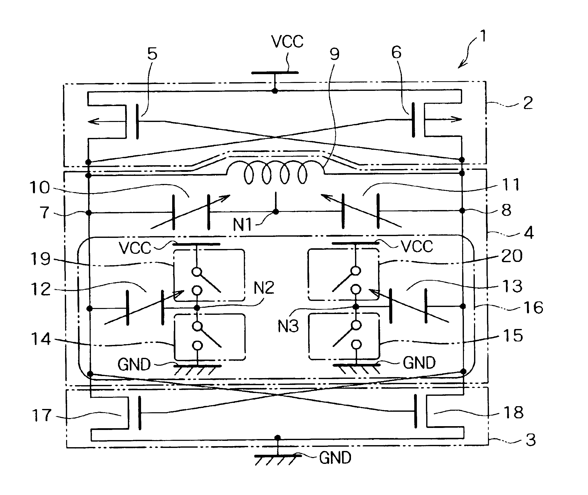
[0026]Moreover, in the present invention, all of the first through fourth switches can be turned off to bring the other electrodes of the second and third variable capacitors into a high impedance state so that the second and third variable capacitors have an extremely small capacitance. This reduces the total capacitance of the resonance unit and thus increases the frequency of the alternating-current signals output from the first and second output terminals. The frequency of the alternating-current signals here shall be a first frequency.
[0027]Now, turning the first and third switches on and the second and fourth switches off can apply the third potential to the other electrodes of the second and third variable capacitors so that the second and third variable capacitors have a predetermined capacitance. This increases the total capacitance of the resonance unit as compared to the foregoing case where the first through fourth switches are all turned off. The alternating-current signals can thus be given a second frequency which is higher than the first frequency.
[0029]As a result, the frequency of the alternating-current signals output from the first and second output terminals can be changed in three levels. It is therefore possible to extend the range of variation in the frequency of the alternating-current signals.
[0030]The first variable capacitor is preferably made of a varactor device to which a control voltage is input and which varies in capacitance in accordance with this control voltage. The second and third variable capacitors are also preferably made of varactor devices to which a control voltage is input and which vary in capacitance in accordance with this control voltage. This makes it possible to achieve variable capacitors which occupy a smaller area.
[0032]According to the present invention, the capacitance of the first variable capacitor can be changed to cause a continuous change in the frequency of the output alternating-current signal. Besides, the first through fourth switches can be controlled to change the frequency of the alternating-current signal in three levels. It is therefore possible to provide a voltage controlled oscillator having a wide range of variation in the frequency of its output signal.

Problems solved by technology

Firstly, the LC-VCO produces smaller noise as compared to the conventional VCOs using a ring oscillator or the like.
The reason for this is that the basic principle of the LC-VCO, i.e., the resonance of the parallel LC tank circuit requires a smaller number of transistors which can cause noise.
In the meantime, one of the drawbacks of the LC-VCO is also the low tuning sensitivity mentioned above.
While it is advantageous in terms of noise as described above, the low tuning sensitivity narrows the range of variation in oscillation frequency and thus makes it difficult to design LC-VCOs of desired oscillation frequencies.
The foregoing conventional technology, however, has the following problem.
Turning on / off the switches 14 and 15, however, can only provide two levels of switching at best, being far from a sufficient range of variation in oscillation frequency.

Method used


Image

  • Voltage controlled oscillator with switched tuning capacitors
  • Voltage controlled oscillator with switched tuning capacitors
  • Voltage controlled oscillator with switched tuning capacitors

Examples


Embodiment Construction

[0040]Hereinafter, an embodiment of the present invention will be described in detail with reference to the accompanying drawings. FIG. 3 is an equivalent circuit diagram showing an LC-VCO according to the present embodiment. FIG. 4 is an equivalent circuit diagram showing a varactor device to be used as variable capacitors. FIG. 5 is a graph for showing the dependence of the capacitance of the varactor device on voltage, in which the abscissa indicates the voltage applied between the terminals of the varactor device, or equivalently, the potential of the G terminal to the SD terminal, and the ordinate indicates the capacitance of this varactor device. FIG. 6 is a graph for showing the range of variation in the oscillation frequency of the LC-VCO according to the present embodiment, in which the abscissa indicates the control voltage to be applied to the variable capacitors and the ordinate indicates the oscillation frequency of the LC-VCO. FIGS. 7A to 7F are graphs for showing the ...


PUM


Abstract

The LC-VCO is provided with two negative resistance units and an LC circuit unit. The LC circuit unit has two output terminals. An inductor is connected between the output terminals, and a series of variable capacitors is connected in parallel with the inductor. In the LC circuit unit, a variable capacitor is connected between one of the output terminals and a node. Another variable capacitor is connected between the other output terminal and another node. Switches are connected between the nodes and a ground potential line, respectively, and between the nodes and a power supply potential line, respectively.

Description

BACKGROUND OF THE INVENTION[0001]1. Field of the Invention[0002]The present invention relates to a voltage controlled oscillator which utilizes resonance of a parallel LC tank circuit. In particular, the invention relates to a voltage controlled oscillator which has a capacitance switch and is capable of changing its oscillation frequency stepwise.[0003]2. Description of the Related Art[0004]Conventionally, voltage controlled oscillators (VCOs) such as a ring oscillator have been used as local oscillators (LOs) in phase-locked loop (PLL) circuits which are used for frequency multiplication and phase synchronization.[0005]For such local oscillators, voltage controlled oscillators utilizing resonance of a parallel LC tank circuit (LC-VCOs) have been used recently. An LC-VCO has an inductor and a variable capacitor which are connected in parallel to form a parallel LC tank circuit. This parallel LC tank circuit causes resonance to oscillate, or output, an alternating-current signal hav...

Claims


Application Information

Patent Timeline
IPC IPC(8): H03B5/00H03B5/12
CPCH03B5/1228H03B5/1212H03B5/1293H03B5/1265H03B5/1253H03B5/1221
Inventor MURAMATSU, YOSHINORI
Owner RENESAS ELECTRONICS CORP
Learn More