
Method for formation of polymer

a polymer and polymer technology, applied in the direction of lamination apparatus, layered products, chemistry apparatus and processes, etc., can solve the problems of reducing the cooling speed of polymer, increasing the cost, scattering to the appearance and feel of molded products, etc., to achieve the effect of reducing the heat conductivity, reducing the cooling speed, and increasing the adiathermancy

Inactive Publication Date: 2006-07-18
JSR CORPORATIOON
View PDF14 Cites 4 Cited by
  • Summary
  • Abstract
  • Description
  • Claims
  • Application Information

AI Technical Summary

Benefits of technology

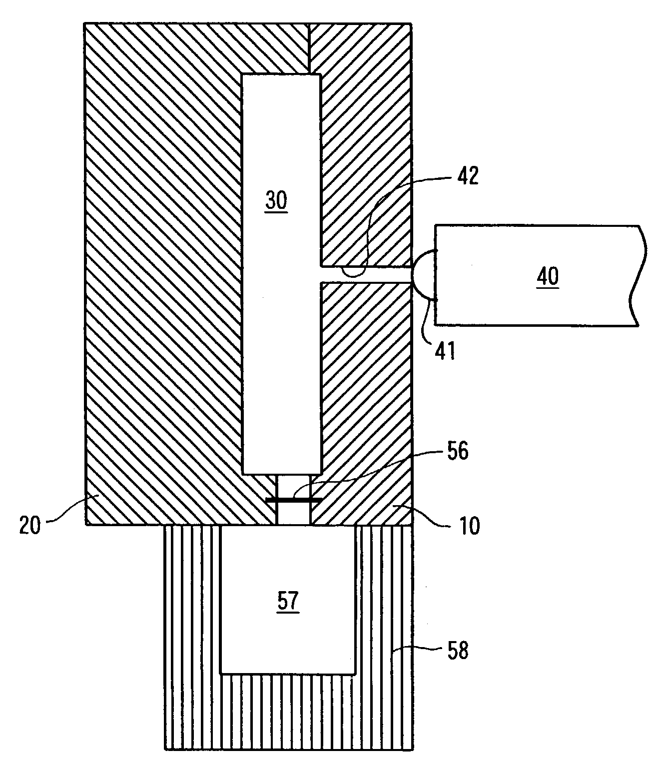
The present invention relates to a method for molding polymers in which a molten polymer containing a foaming agent is put into a mold cavity and gas is injected into the polymer to contact it in the molten state close to the mold cavity surface by utilizing the pressure of the gas. The gas is exhausted to fill the space occupied until then by the gas with the polymer and foam it, resulting in a molded product with the outside shape fit to the inside shape of the mold cavity and the inside thereof foamed. The invention solves problems of previous techniques such as deformation of the mold cavity and uneven thickness of the foam part.

Problems solved by technology

Firstly, as the molding space (i.e., mold cavity) is enlarged and deformed in the process of molding, it may be difficult to precisely transfer the inside shape of a mold cavity to the outside shape of a molded product, and thus dimensional precision may be lowered. Furthermore, in order to precisely transfer the inside shape of a mold cavity to the outside shape of a molded product, it is necessary to precisely control the enlargement of the molding space, and this will increase the cost.
Secondly, as the enlargement of the molding space is different from one portion to another, the thickness of the skin layer 161 and the expansion ratio of the foam part 162 vary from one position to another. As a result, the appearance, feel and the like of a molded product vary from one position to another. For example, for a molded product with cross-sectional shape as illustrated in FIG. 5, while the thickness of the vertical portion as viewed in this figure is changed from T0 to T1 when the molding space is enlarged, the thickness of the upper and lower horizontal portions remains unchanged at t0. This inevitably causes scattering to the appearance and feel of the molded product between the vertical portion and the upper and lower horizontal portions.

Method used


Image

  • Method for formation of polymer
  • Method for formation of polymer
  • Method for formation of polymer

Examples


example 1

According to the First Preferred Embodiment

[0106]The above-described pellet-blended thermoplastic elastomer and foaming agent were pellet-blended and mold-injected and gas was injected at the same time, and then the gas was slowly exhausted. As a result, a molded product with adequate appearance and feel and the foamed inside was obtained.

example 2

According to the Second Preferred Embodiment

[0107]The above-described pellet-blended thermoplastic elastomer and foaming agent were pellet-blended and mold-injected, and after the mold cavity was filled with the molten polymer, the shutter was opened to increase the volume of the molten polymer. As a result, a molded product with adequate appearance and feel and the foamed inside was obtained.


PUM

PropertyMeasurementUnit
thermal conductivityaaaaaaaaaa
thicknessaaaaaaaaaa
thicknessaaaaaaaaaa

Abstract

Objects of the present invention are to provide a method for molding polymers to be able to mold products each of which has an outer shape transferred accurately from the shape of the inside of a mold, exhibits high dimensional accuracy and is uniform in the thickness of its surface skin layer and the expansion ratio in its foamed inside.A molten polymer 60 is injected into a cavity 30 and simultaneously gas is pressed to the inside of the molten polymer 60 to contact the polymer close to the surface of the mold, and then gas is exhausted while maintaining the shape inside the mold, to thereby mold a polymer formed product in which a surface skin layer 61 and a foamed inside 62 having cushioning property are formed in one piece.

Description

FIELD OF THE INVENTION[0001]The present invention relates to methods for molding polymers, and more particularly to methods for molding a product in which a skin layer and a cushiony inside are formed in one piece by using the same polymers, whereas the term “polymers” refers to “thermoplastic resins,”“thermoplastic elastomers,”“thermosetting resins” or “cross-linked elastomers.”RELATED ART[0002]Molded products, each having a skin layer and a cushiony inside, are used for various purposes, such as automotive interior panels to meet the requirements of posh appearance and softness of touch.[0003]The molded products, each of which a skin layer and a cushiony inside are formed in one piece, can be molded by covering a cushiony material, such as polyurethane foam, with vinyl chloride or the like.[0004]Recently, in response to requirements of high recycling efficiency and efficient cost reduction by simplifying processes, molded products, each having a skin layer and a cushiony inside an...

Claims


Application Information

Patent Timeline
Patent Type & Authority Patents(United States)
IPC IPC(8): B29C44/02B29C44/06C08J9/06B29C43/00B29C43/02B29C43/10B29C44/04B29C45/00
CPCB29C43/003B29C43/10B29C44/04B29C44/0415B29K2105/043B29C2043/3227B29C2043/566
Inventor KURIHARA, FUMIOKOUJINA, JUNJIMORIKAWA, AKIHIKOAOYAMA, AKIOMAEDA, MASAKI
Owner JSR CORPORATIOON
Learn More