
Multi-path detection circuit and method for a CDMA receiver

a detection circuit and multi-path technology, applied in the field of cdma (code division multiple access) receivers, can solve the problems of increasing current consumption, long time, and disadvantageous sort algorithm of binary tree search, and achieve the effect of reducing the cycle number

Active Publication Date: 2006-07-11
NEC CORP
View PDF29 Cites 13 Cited by
  • Summary
  • Abstract
  • Description
  • Claims
  • Application Information

AI Technical Summary

Benefits of technology

The invention provides a multi-path detection circuit for a CDMA receiver that can quickly and efficiently process multi-path detection. The circuit can detect multiple path positions simultaneously and can measure the delay profile of a multi-path to determine its timing. The circuit can also renew maximum value information to detect peaks in the delay profile data. The technical effects of this invention include improved multi-path detection speed, reduced cycle number for detecting peaks, and improved accuracy in measuring the timing of a multi-path.

Problems solved by technology

One of the problems is that, in order to search some paths from multi-paths with reference to the measured delay profile, maximum search operations should be executed by the number of the searched paths or sort processing should be executed over whole profile data.
Consequently it takes a long time to search the multi-path, which brings about an increase of current consumption.
This is because the delay profile generally includes a great amount of data and a processing time inevitably becomes long so as to search a plurality of peaks from the whole data of the delay profile.
Therefore, a sort algorithm of the binary tree search is disadvantageous in that data included in a single peak are repeatedly detected.
This shows that the first problem can not be always solved even when usual high speed sort algorithm is used.
Therefore, the multi-path detection circuit mentioned in the first reference is disadvantageous in that a processing time becomes long as an increase of the peak number of the detected peaks.
However, no consideration is made at all about a multi-path detection circuit and its structure.
However, no teaching is made in the third reference about executing multi-path detection at a high speed.

Method used


Image

  • Multi-path detection circuit and method for a CDMA receiver
  • Multi-path detection circuit and method for a CDMA receiver
  • Multi-path detection circuit and method for a CDMA receiver

Examples


first embodiment

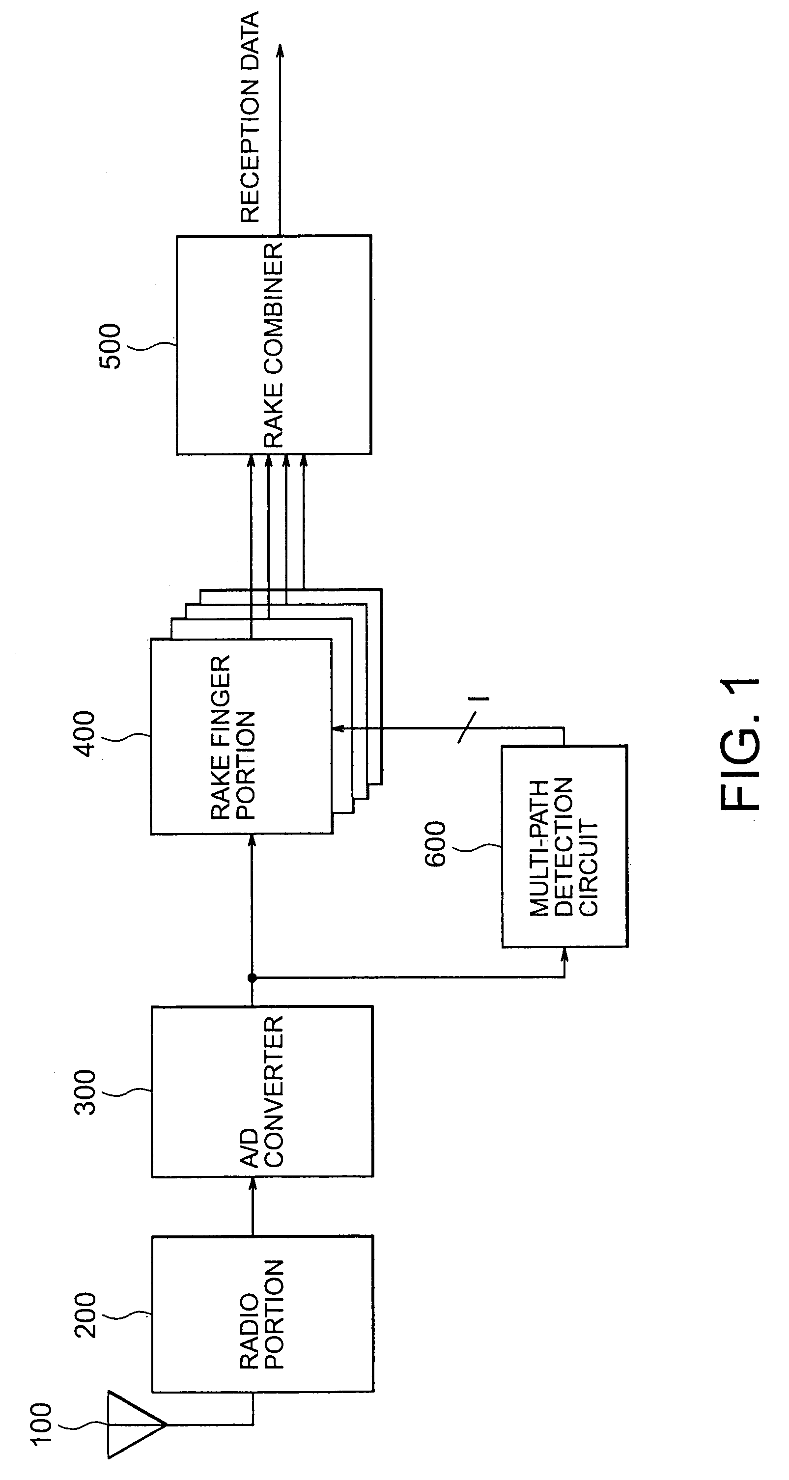
[0046]Referring to FIG. 1, a CDMA receiver will be described which includes a multi-path detection circuit 600 according to this invention. In addition to the multi-path detection circuit 600, the illustrated CDMA receiver has an antenna portion 100, a radio portion (high frequency reception section) 200, an A / D converter 300, a rake finger portion 400, and a rake combiner or synthesizer 500.

[0047]A sequence of data is transmitted as a radio signal and is received as a reception signal through the antenna portion 100 by the CDMA receiver. The reception signal is subjected by the radio portion 200 to frequency conversion (down conversion) and is converted by the A / D converter 300 into a digital signal from an analog signal. The digital signal output from the A / D converter 300 is supplied to the multi-path detection circuit 600.

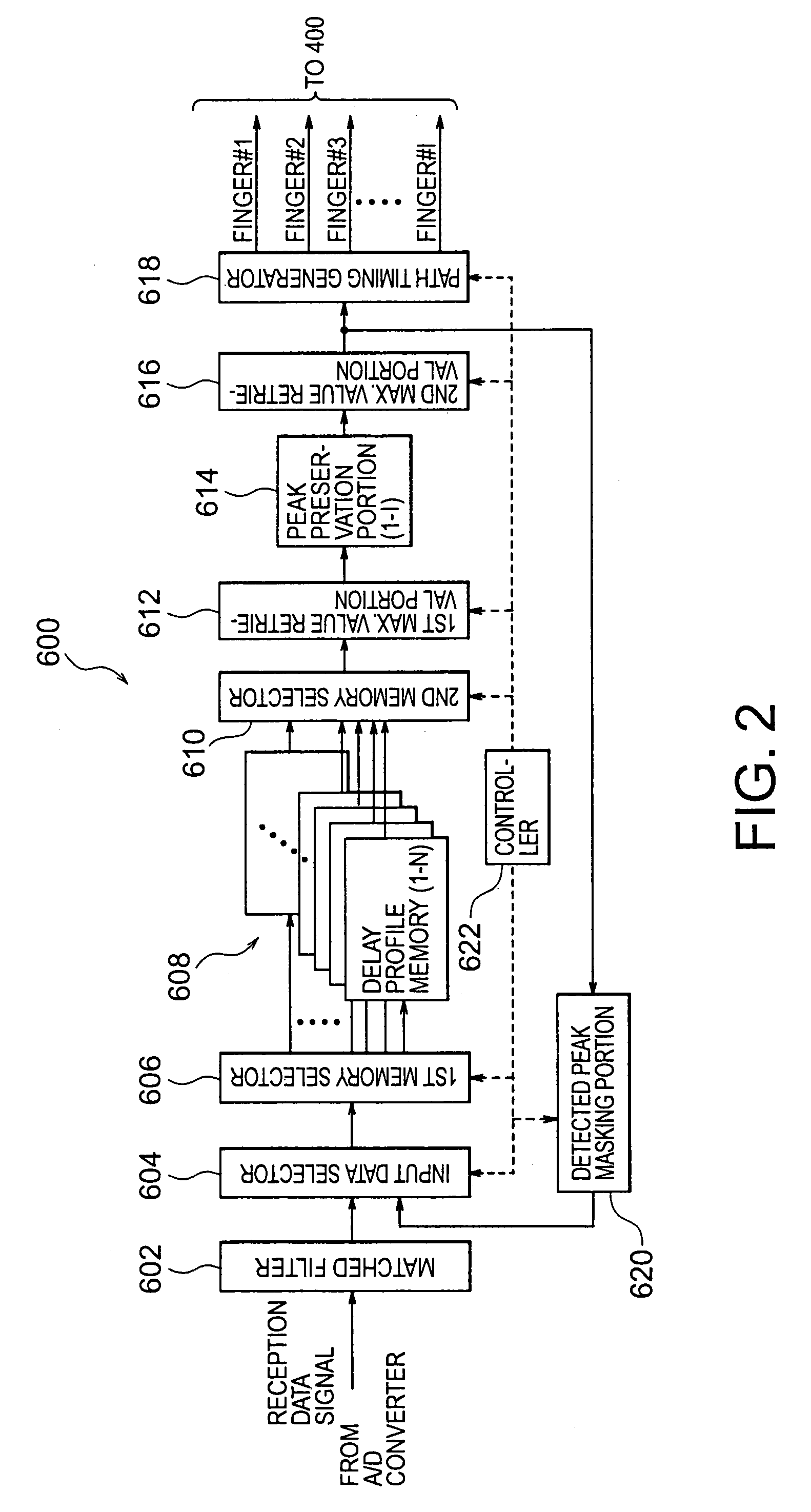
[0048]As will be mentioned later, the multi-path detection circuit 600 measures a delay profile of a propagation path from the digital signal and detects each ...

second embodiment

[0080]Referring to FIG. 10, a multi-path detection circuit 600A according to this invention is similar in structure to that illustrated in FIG. 1 except that a threshold detection portion 624 is added between the second maximum value retrieval portion 616 and the path timing generator 618 and that a control operation of a controller 622A is somewhat different from that of the controller 622 illustrated in FIG. 2.

[0081]As shown in FIG. 10, inclusion of the threshold detection portion 624 is effective to shorten a detection time. Specifically, the threshold detection portion 624 has a predetermined threshold level defined by a reference correlation level and compares a peak value with the predetermined threshold level. When the threshold detection portion 624 detects a peak value that is lower than the predetermined threshold level, a stop signal is sent from the threshold detection portion 624 to the controller 622A so as to stop peak detection processing at a time instant of detecti...


PUM


Abstract

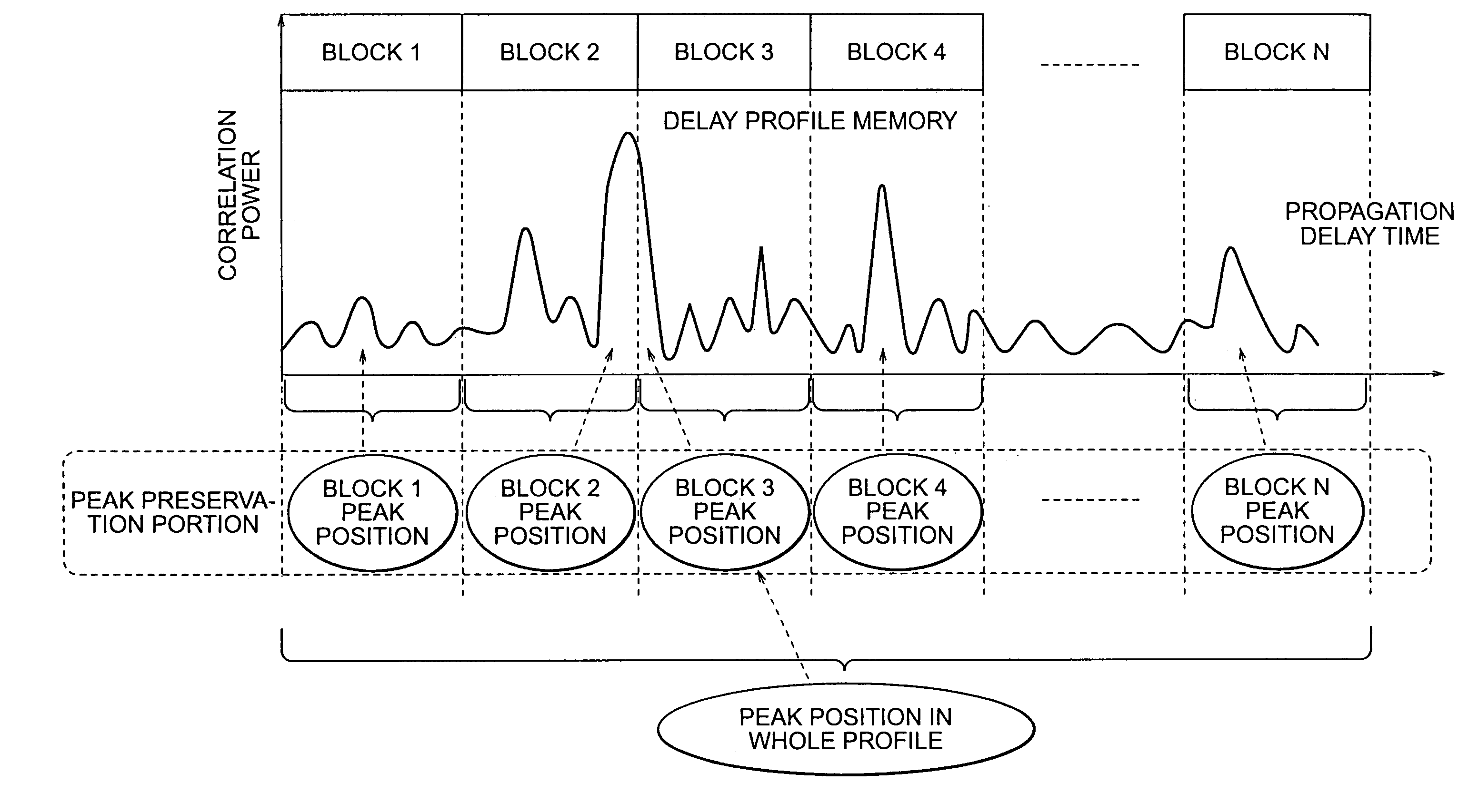
In a multi-path detection circuit for use in a CDMA communication system, a first peak is detected by searching a maximum value over a whole of data blocks composed of delay profile data. A second and the following peaks are detected by carrying out maximum value searching operation again only about a data block that is renewed in the delay profile data. As the remaining data blocks, a maximum value searched a previous time is preserved and used a next time and, therefore, reduction is possible in connection with the number of detection cycles necessary for detecting the second and the following peaks.

Description

BACKGROUND OF THE INVENTION[0001]This invention relates to a CDMA (Code Division Multiple Access) receiver and, in particular, to a multi-path detection method and circuit that is used in the CDMA receiver.[0002]Conventionally, a wide variety of cellular communication systems have been proposed and used in the world. Among others, recent attention has been focused onto a cellular mobile CDMA system that has a specific spread code assigned to each channel and that will be simply called a CDMA system hereinafter. In such a CDMA system, a modulated radio wave is generated by spreading a transmission signal by the specific spread code to obtain a spread signal and by modulating the same carrier frequency by the spread signal and is transmitted from a transmission side (transmission terminal) to a reception one (reception terminal).[0003]Responsive to the modulated radio wave, a CDMA receiver on the reception side executes synchronizing operation by the use of each of the specific spread...

Claims


Application Information

Patent Timeline
Patent Type & Authority Patents(United States)
IPC IPC(8): H04B1/69H04B1/707H04B1/7113H04B1/7117H04B7/08H04B7/26H04W28/18
CPCH04B1/7113H04B1/7117
Inventor OHSUGE, MICHIHIRO
Owner NEC CORP
Learn More