
Head mounted display system

a display system and display head technology, applied in the field of head mounted display systems, can solve the problems of general limitation of the resolution the size and weight of the display head, etc., and achieve the effect of convenient use, convenient and convenient operation, and convenient us

Inactive Publication Date: 2006-07-11
KOPIN CORPORATION
View PDF22 Cites 71 Cited by
  • Summary
  • Abstract
  • Description
  • Claims
  • Application Information

AI Technical Summary

Benefits of technology

The present invention is a head mounted optical support system that uses a single-crystal material to produce a high-density active matrix array. The system is more compact, has lighter weight, and a lower cost than existing head mounted displays. To achieve the desired level of resolution, a short focal length lens system is used, which results in a lens-to-display distance of less than one inch. The display can be a transmission type display or an emission type display, such as an active matrix electroluminescent display or active matrix of light emitting diodes. The invention also includes a projected view active matrix display in which different polarization components of light are separated, one component being directed to the left eye, and another component being directed to the right eye. Another preferred embodiment utilizes an active matrix display in which the pixel size increases across the display to provide a wide angle field of view display. The display can be fabricated as a visor with a number of displays which are tied together and positioned on a flat or curved plastic visor.

Problems solved by technology

Head mounted displays are generally limited by their resolution and by their size and weight.

Method used


Image

  • Head mounted display system
  • Head mounted display system
  • Head mounted display system

Examples


Embodiment Construction

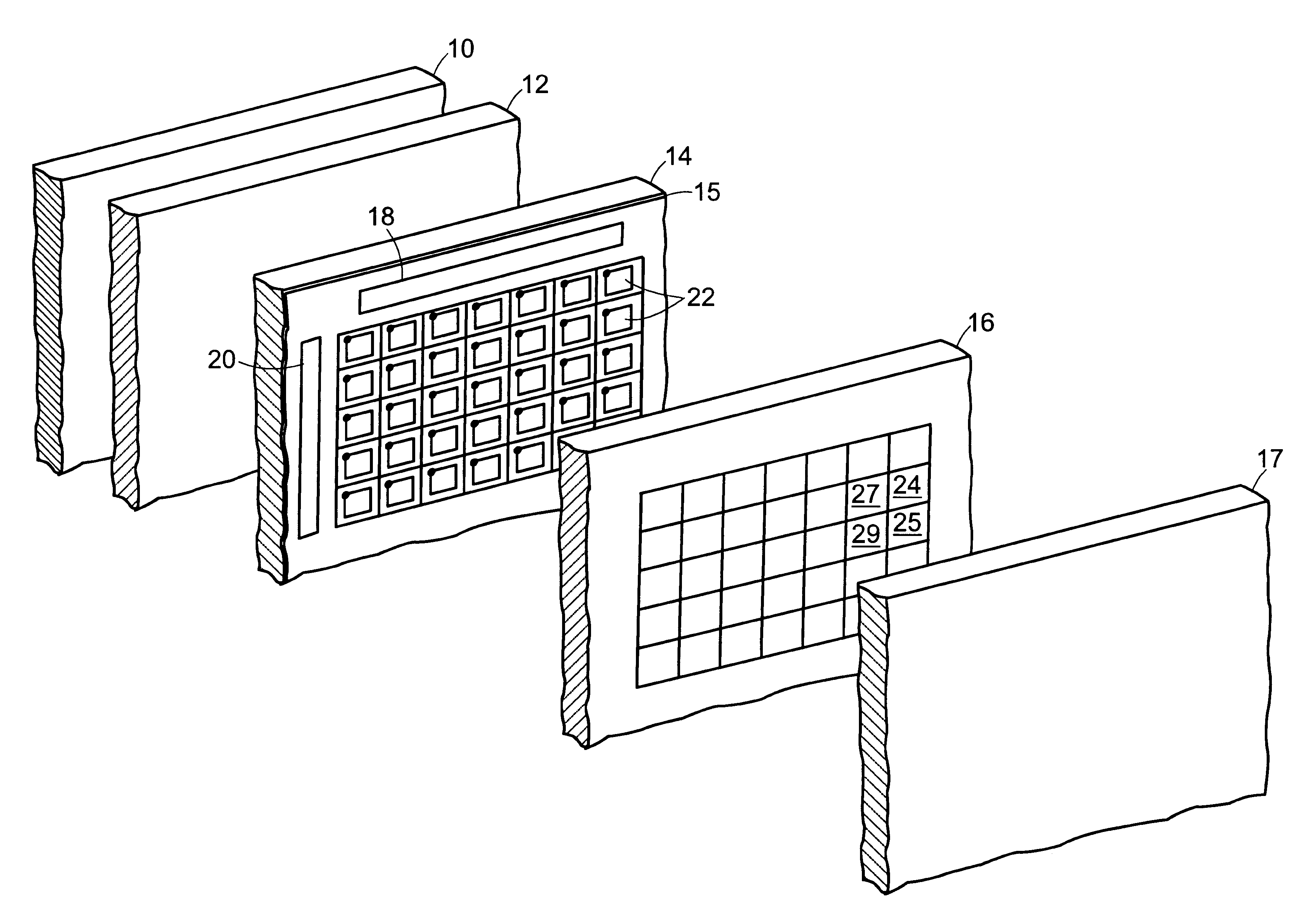
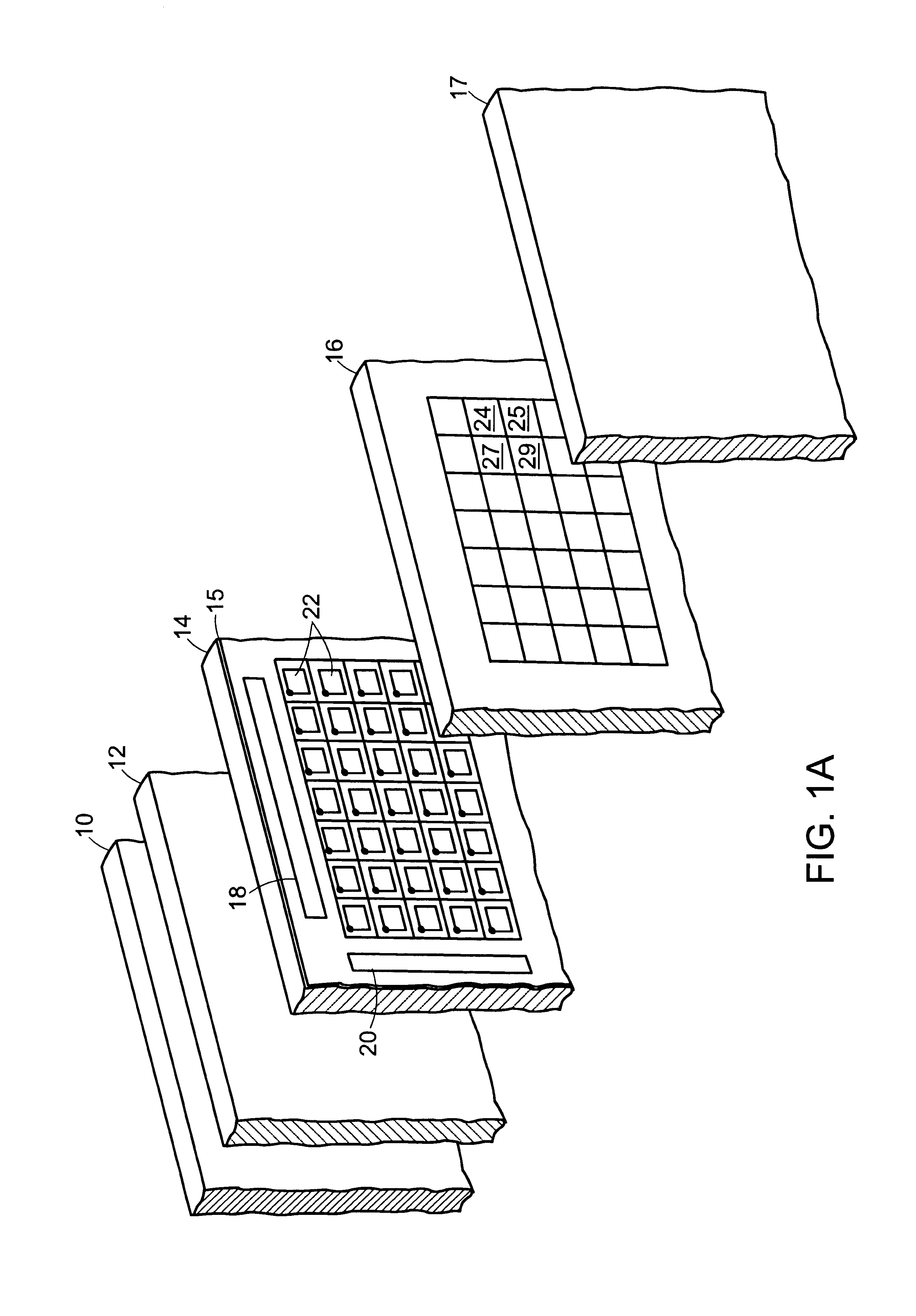
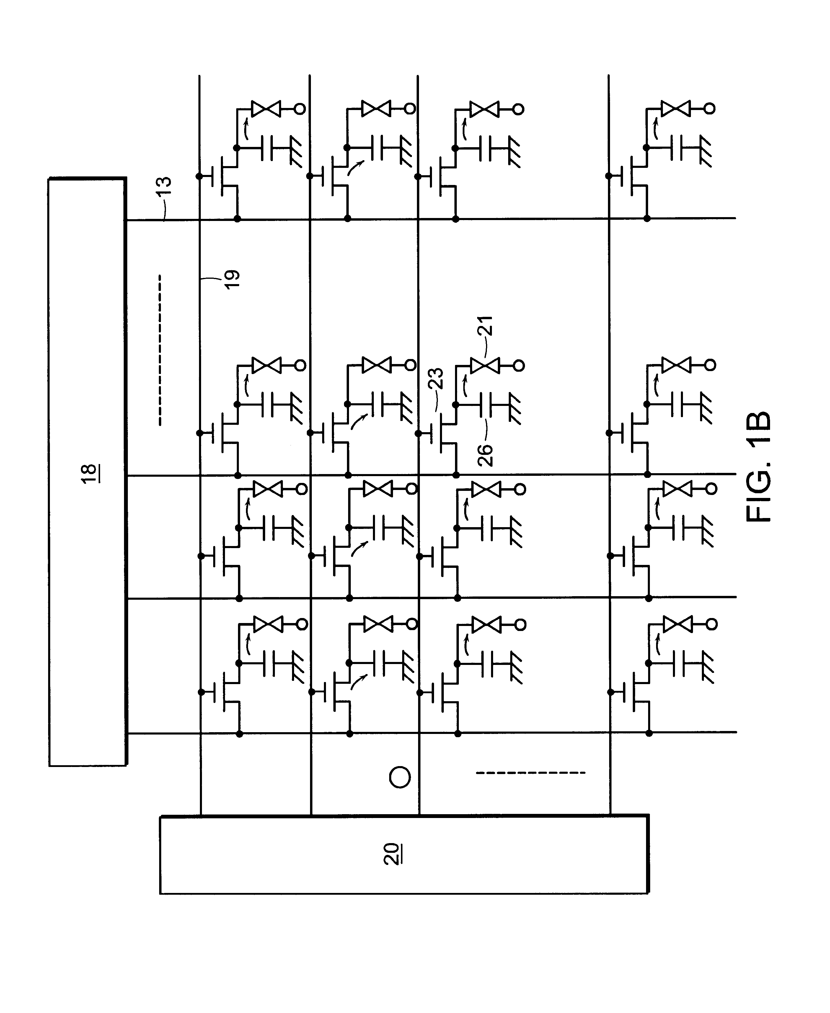
[0053]A preferred embodiment of the invention is illustrated in the perspective view of a panel display in FIG. 1A. The basic components of the display include a light source 10 that can be white or some other appropriate color, a first polarizing filter 12, a circuit panel 14, a filter plate 16 and a second polarizing filter 17, which are secured in a layered structure. A liquid crystal material (not shown) is placed in a volume between the circuit panel 14 and the filter plate 16. An array of pixels 22 on the circuit panel 14 are individually actuated by a drive circuit having first 18 and second 20 circuit components that are positioned adjacent the array such that each pixel can produce an electric field in the liquid crystal material lying between the pixel and a counterelectrode secured to the color filter plate 16. The electric field causes a rotation of the polarization of light being transmitted across the liquid crystal material that results in an adjacent color filter ele...


PUM

PropertyMeasurementUnit
diameteraaaaaaaaaa
diameteraaaaaaaaaa
diameteraaaaaaaaaa

Abstract

A head mounted display system including a high resolution active matrix display which reduces center of gravity offset in a compact design. The active matrix display can be either a liquid crystal display or a light emitting display.

Description

RELATED APPLICATION[0001]This is a Continuation of U.S. patent application Ser. No. 07 / 971,352 filed on Nov. 4, 1992, which is now abandoned, which is a continuation-in-part of application Ser. No. 07 / 944,207 filed on Sep. 11, 1992, now U.S. Pat. No. 5,444,557 which is a Continuation-In-Part application of U.S. Ser. No. 07 / 823,858 filed on Jan. 22, 1992 which is now abandoned and is also a Continuation-In-Part of U.S. patent application Ser. No. 07 / 643,552 filed on Jan. 18, 1991, now U.S. Pat. No. 5,300,788, and is also a Continuation-In-Part of U.S. patent application Ser. No. 07 / 872,297, filed Apr. 22, 1992, now U.S. Pat. No. 5,317,436, which is a Continuation-In-Part of U.S. patent application Ser. No. 07 / 636,602, filed Dec. 31, 1990, now U.S. Pat. No. 5,206,749, all of which are incorporated herein by reference.BACKGROUND[0002]Head mounted display systems have been developed for a number of different applications including use by aircraft pilots and for simulation. Head mounted ...

Claims


Application Information

Patent Timeline
Patent Type & Authority Patents(United States)
IPC IPC(8): G09G5/00A61B3/113G02B5/30G02B27/00G02B27/01G02F1/1333G02F1/1335G02F1/1347G02F1/1362G09G3/20G09G3/30G09G3/32G09G3/36H01L21/77H01L21/822H01L21/84H01L25/075H01L27/06H01L27/12H01L27/15H01L29/786H01L33/00H01S5/02H01S5/42H04N5/70H04N5/74H04N9/31H05B33/12
CPCA61B3/113G02B27/0093G02B27/017G02B27/0172G02F1/133526G02F1/13454G02F1/1362G02F1/136209G02F1/136277G09G3/30G09G3/36H01L21/8221H01L24/96H01L25/0756H01L27/0688H01L27/12H01L27/156H01L29/786H01L29/78603H01L29/78633H01L29/78648H01L33/0062H04N5/7441H04N9/312H04N9/3141H04N9/3197H05B33/12H01L27/1281G02B5/30G02B2027/0132G02B2027/0136G02B2027/0138G02B2027/0187G02B2027/0198G02F1/13336G02F1/13473G02F2001/13613G02F2202/105G02F2203/01G09G3/2014G09G3/32G09G3/3607G09G3/3614G09G3/3648G09G2300/023G09G2310/0259G09G2320/0233G09G2320/041G09G2320/043G09G2340/0464G09G2370/042H01L29/78612H01L29/78618H01L2221/68359H01L2221/68363H01L2924/01005H01L2924/01013H01L2924/01015H01L2924/01047H01L2924/01049H01L2924/01052H01L2924/01074H01L2924/01077H01L2924/01082H01L2924/04953H01L2924/10329H01L2924/13091H01L2924/14H01L2924/19041H01L2924/30105H01L2924/3025H01S5/0217H01S5/423H04N5/70H04N5/7491H01L2924/01006H01L2924/01023H01L2924/01033H01L2924/01072H01L2924/00011H01L2924/12043H01L2924/3511G02F1/13613H01L2224/80001H01L2924/00
Inventor SPITZER, MARK B.GALE, RONALDJACOBSEN, JEFFREY
Owner KOPIN CORPORATION
Learn More