System and method for determining freight container locations
a technology for determining the location of freight containers, applied in the field of system and method for tracking inventory and freight, can solve problems such as adding battery bulk
- Summary
- Abstract
- Description
- Claims
- Application Information
AI Technical Summary
Benefits of technology
Problems solved by technology
Method used
Image

Examples
first embodiment
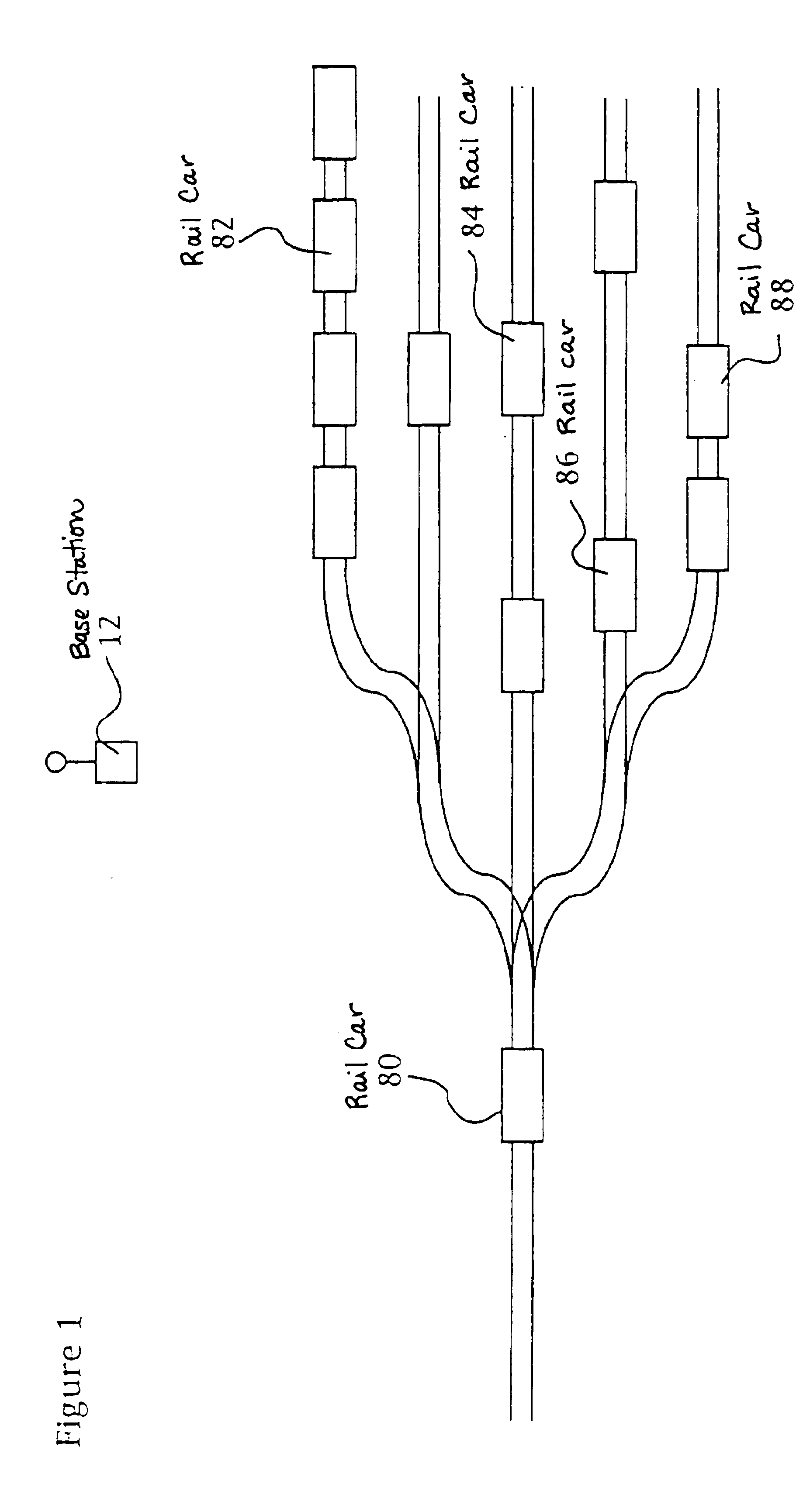
[0027]Turning to the drawings, the system of the present invention includes a remote unit 10, base station 12, and calibration system 40. A remote unit 10 is attached to a freight container in a freight yard and intermittently reports its position to the base station 12, at least while the container remains in the freight yard.
[0028]As shown in FIG. 3, the remote unit 10 include a packet radio system 20, a GPS antenna 21 and receiver 22, a CPU 24, storage 25, battery 26 and a control device 28. The GPS receiver 22 is preferably the multi-channel receiver such as the SV-6 Model or core module II made by Trimble Navigation of Sunnyvale, Calif. Other commercially available substitutes are acceptable such as made by Magellan or Rockwell / Collins. The antenna 21 is either remote or internal to the receiver 22, but in any event is mounted on the housing of the remote unit 10 for an upward look angle for optimum GPS signal reception. That is, the remote unit 10 is designed for mounting on t...
second embodiment
[0037]The embodiment illustrated in FIG. 6 is useful to illustrate several alternatives that may be incorporated into the first embodiment illustrated in FIG. 3. The GPS “engine” is eliminated in the remote units 10. Rather, each remote unit 10 comprises a GPS repeater, such as a Tidget GPS sensor made by Navsys Corp. of Edinburgh, Scotland. The repeater 50 operates to receive the GPS raw data timing signals from the GPS satellites, digitize and compress the timing signals. Preferably, the repeater 50 can be set to look at a certain number of satellites, e.g. 5 satellites. The satellite timing signals are not processed. Instead, the signals are amplified and periodically relayed to the base station 12 via the radio interface 20.
[0038]In FIG. 6, the remote unit 10 includes a separate timer 62 and motion detector 54 for initiating operation. That is, the timer 52 can be set to initiate operation of the remote unit 10 at preset times. Additionally, or alternatively, the motion detector...
third embodiment
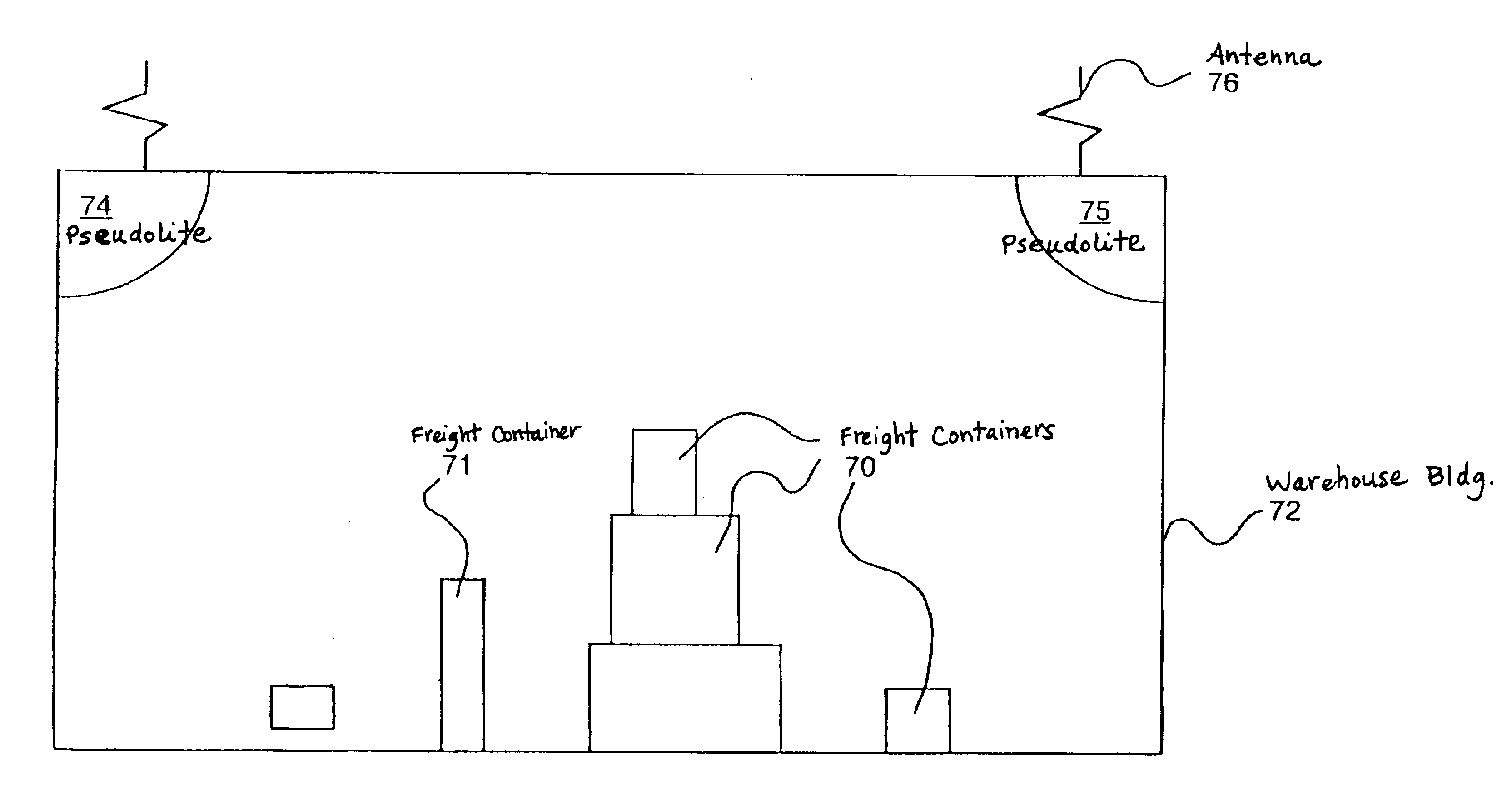
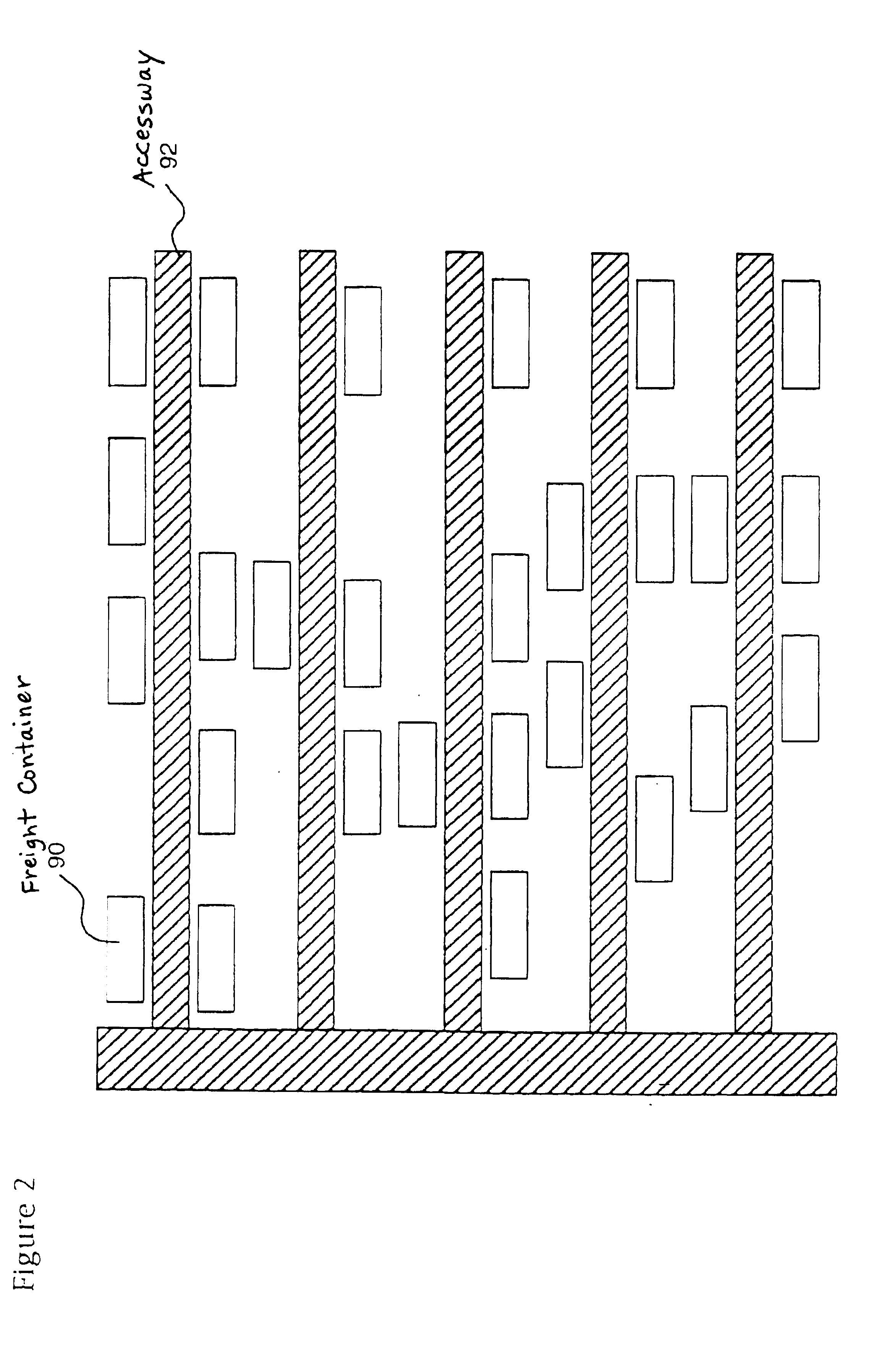
[0043]FIG. 7 illustrates a number of freight containers 70 inside of a warehouse building 72. Remote units 10 in accordance with the first or second embodiments, FIGS. 3 and 6, are attached to the freight containers 70. Because the freight containers are inside of a building 72, reception of GPS signals from the satellite constellation is not normally possible. Therefore, pseudolites 74,75 are employed within the building 72 and operate like conventional GPS satellites. Each pseudolite includes an antenna 76 to receive GPS time from the GPS satellites. This eliminates the necessity for an atomic clock in the pseudolites 74 (with a concomitant reduction in cost).
[0044]While two pseudolites 74,75 are sufficient to give accurate 3D position to the remote receivers 10, the system of FIG. 7 preferably uses three pseudolites. The elevation of the warehouse floor is known and freight containers may be positioned on the floor which simplifies position calculations. However, because of the c...
PUM
 Abstract
Description
Claims
Application Information
 - R&D
- Intellectual Property
- Life Sciences
- Materials
- Tech Scout
- Unparalleled Data Quality
- Higher Quality Content
- 60% Fewer Hallucinations
Browse by: Latest US Patents, China's latest patents, Technical Efficacy Thesaurus, Application Domain, Technology Topic, Popular Technical Reports.
© 2025 PatSnap. All rights reserved.Legal|Privacy policy|Modern Slavery Act Transparency Statement|Sitemap|About US| Contact US: help@patsnap.com