High phase order electrical rotating machine with distributed windings

a technology of distributed windings and rotating electrical machines, which is applied in the direction of motor/generator/converter stopper, dynamo-electric converter control, etc., can solve the problems of concentrated windings that cannot be used in the stator of concentrated windings, and the use of concentrated windings is only useful, so as to achieve the effect of changing the impedance of the machine and economic production

Inactive Publication Date: 2006-07-11
BOREALIS TECH LTD
View PDF43 Cites 13 Cited by
  • Summary
  • Abstract
  • Description
  • Claims
  • Application Information

AI Technical Summary

Benefits of technology

[0020]It is an advantage of the present invention that an electrical rotating machine of more than three phases can be built that is able to use selected low order spatial harmonics but which filters out many higher order spatial harmonics.
[0021]It is an advantage of the present invention that an electrical rotating machine can have electrically variable impedance. When a high phase order machine is connected with a mesh connection to the inverter drive, then low-order harmonics added to the waveform can significantly change the impedance of the machine. At the same time, higher-order spatial harmonics that are less useful and often detrimental, are filtered out of the machine.
[0022]It is an advantage of the present invention that the same electrical rotating machine can be used for both high speed and traction applications.
[0023]It is an advantage of the present invention that the drive circuitry may be economically produced.

Problems solved by technology

However the use of concentrated windings comes at a significant cost.
Additionally, if the phase count is not sufficient, then a concentrated winding electrical machine does not make sufficient use of its stator.
Concentrated winding induction machines are thus only useful when the phase count can be large.
Three phase systems cannot in general use concentrated windings, with the exception of extremely high pole count systems, in which the pole / phase group (PPG) might be limited to a single slot.
Inductors in the various slots somewhat counter the magnetic field produced by the series connected inductors in other slots, reducing the effective current flowing in the inductors, and thus reducing the efficiency of producing a magnetic field.
This is because a three-phase machine does not fully sample the high frequencies of the temporal harmonics of the drive waveform.

Method used


Image

  • High phase order electrical rotating machine with distributed windings
  • High phase order electrical rotating machine with distributed windings
  • High phase order electrical rotating machine with distributed windings

Examples


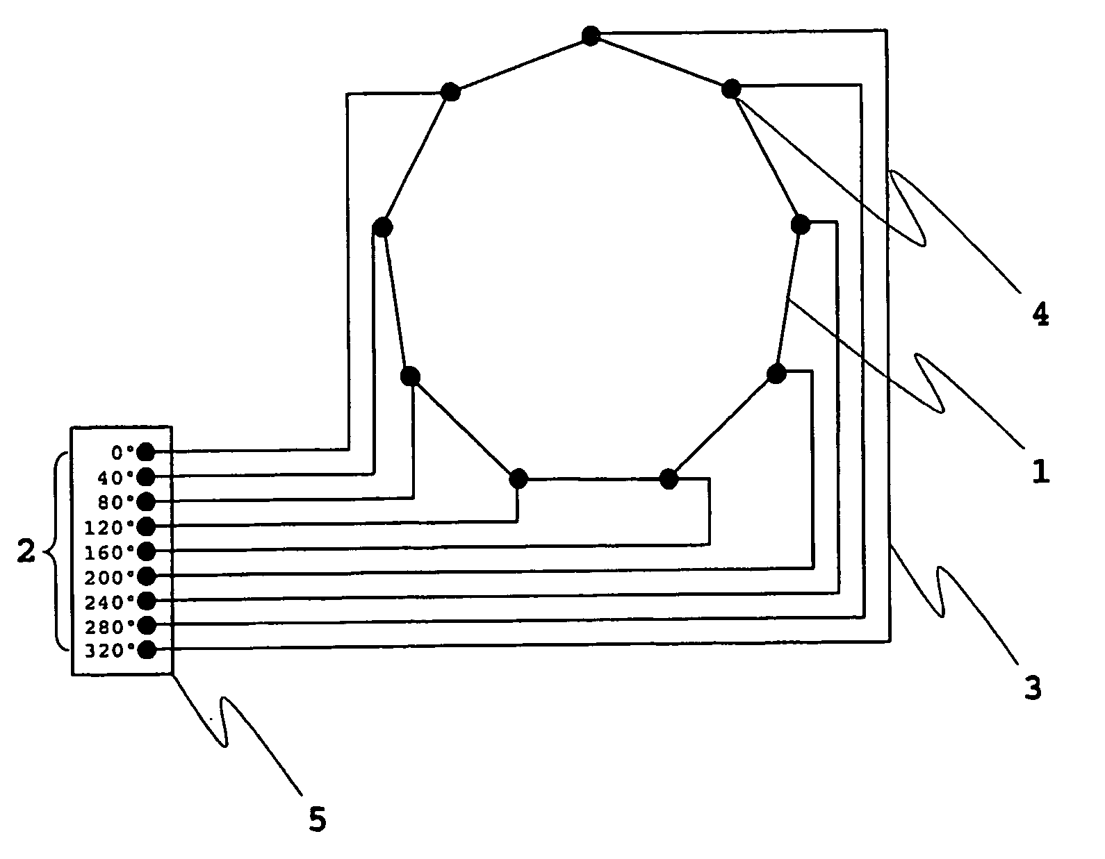
Embodiment Construction

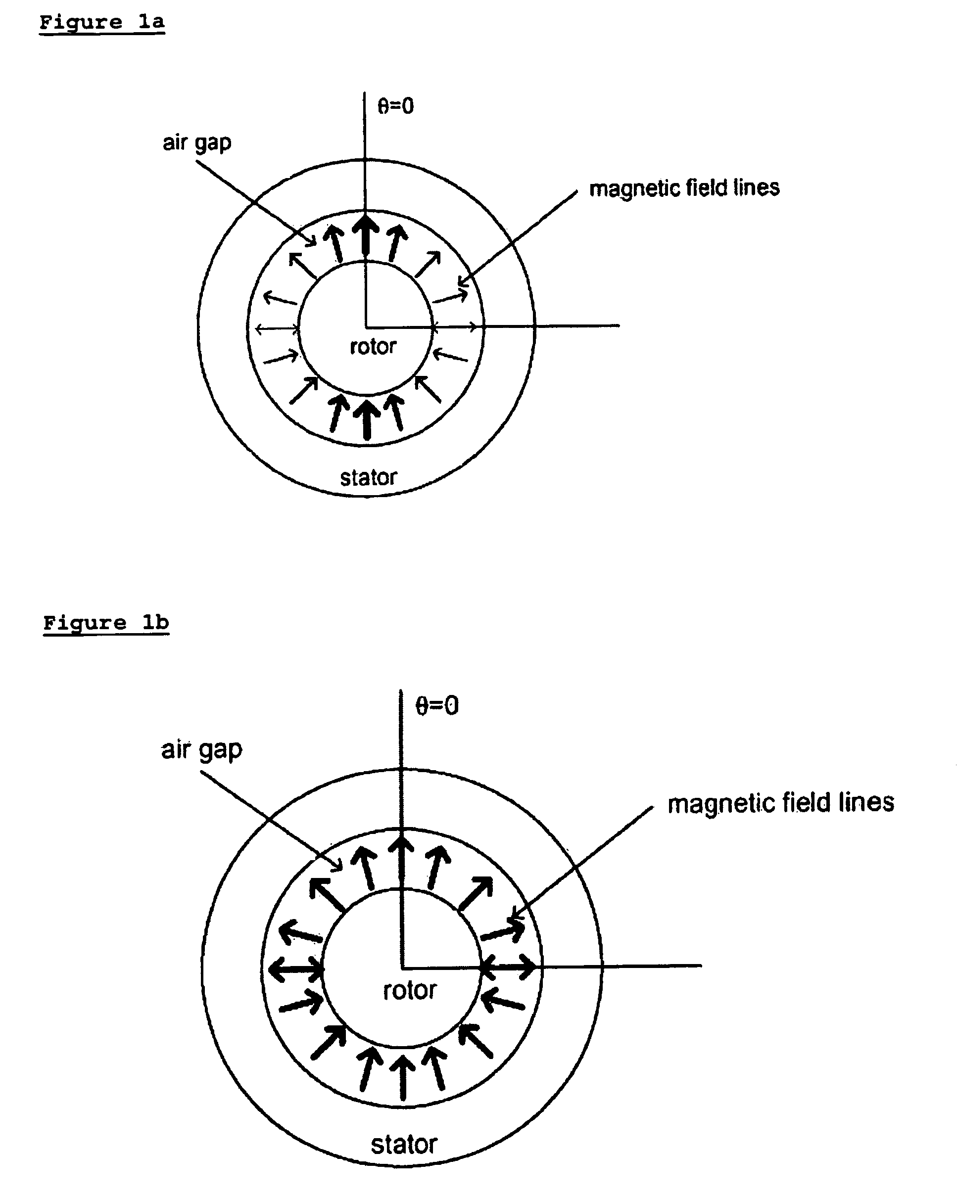
[0045]The current flowing in the stator slots produces the rotating magnetic field of an electrical rotating machine. This current flow changes over time, causing the overall structure of the stator current distribution to change over time and rotate. In the ideal case, the stator current distribution is fixed in shape, but simply rotating. The various phases feeding the motor can be thought of as spatially sampling this current distribution, and the physically distributed turns of winding in the stator can be thought of as the necessary reconstruction filter. Each phase describes the current flowing at one location in each pole of the stator, and the winding distribution acts to smooth out this current flow appropriately.

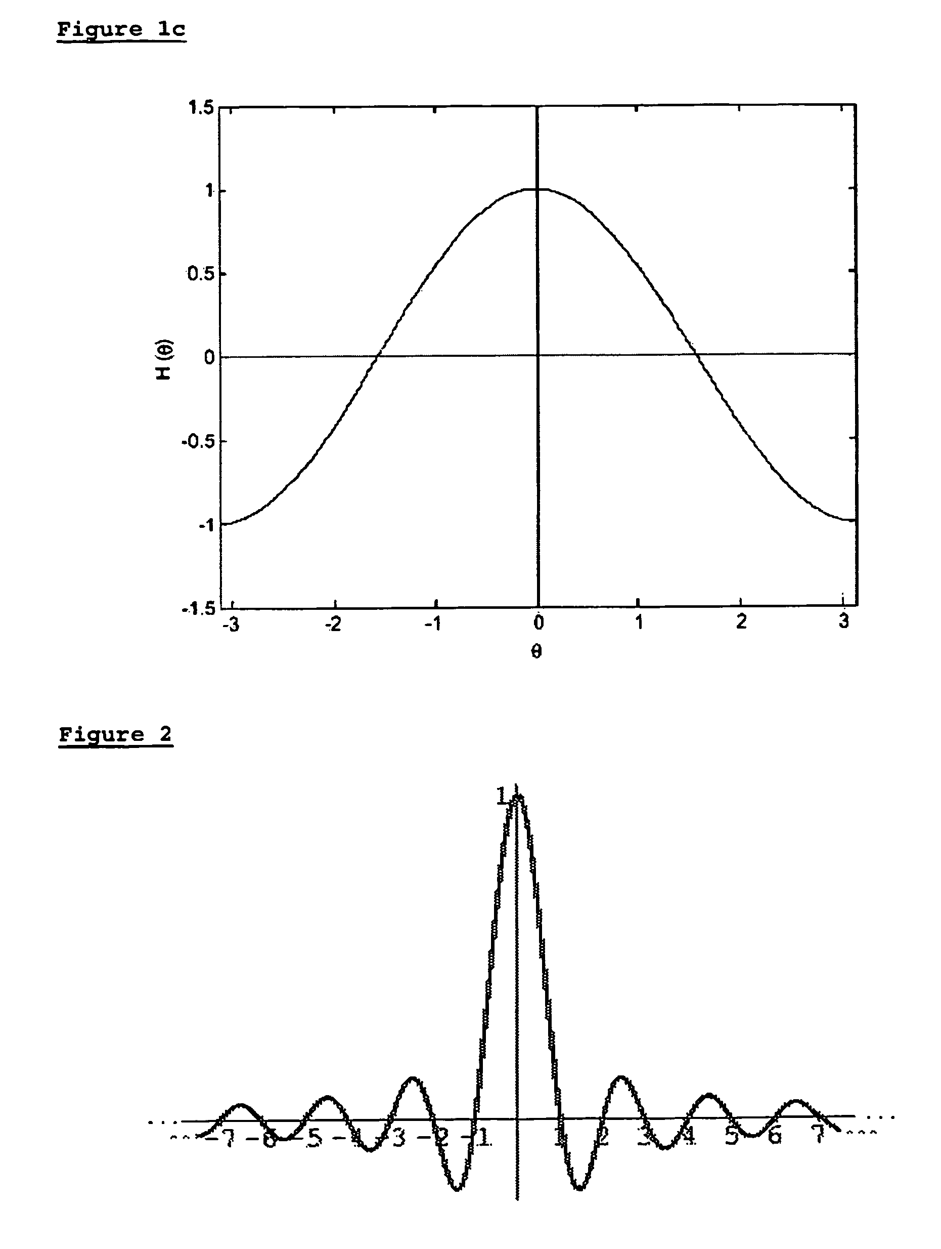
[0046]Spatial harmonics, or air-gap harmonics, are harmonic fields generated by the non-sinusoidal nature of the field generated by each winding. When spatial harmonics are excited by the fundamental drive currents, they produce a secondary rotating field that rota...


PUM


Abstract

A rotating induction machine, containing five or more different phases, having windings distributed according to a sinc function with a cutoff frequency allowing low-order spatial harmonics but preventing higher order spatial harmonics from flowing. In a preferred embodiment, the machine is connected to drive means capable of injecting third harmonic into the machine. In a further preferred embodiment, the windings are connected to the drive means with a mesh connection and the machine has five phases.

Description

CROSS-REFERENCE TO RELATED APPLICATION[0001]This application is the U.S. national stage application of International Application PCT / US03 / 10346, filed Apr. 3, 2003, which international application was published on Oct. 16, 2003, as International Publication WO03085801 in the English language. The International Application claims the benefit of U.S. Provisional Application No. 60 / 370,484, filed Apr. 3, 2002. The above-mentioned patent applications are assigned to the assignee of the present application and are herein incorporated in their entirety by reference.TECHNICAL FIELD[0002]The present invention relates to winding distributions in rotating electrical machines.BACKGROUND ART[0003]Previously disclosed, in U.S. Pat. Nos. 6,570,361 and 6,351,095, have been High Phase Order electrical rotating machine designs. Of specific interest is the application “HIGH PHASE ORDER MOTOR WITH MESH CONNECTED WINDINGS,” Ser. No. 09 / 713,654, filed Nov. 15, 2000, now U.S. Pat. No. 6,657,334, which di...

Claims


Application Information

Patent Timeline
Patent Type & Authority Patents(United States)
IPC IPC(8): H02P21/04H02P27/00H02K3/28H02K11/04H02K17/12H02P25/22
CPCH02K3/28H02P25/22H02K17/12H02K11/0073H02K11/33
Inventor EDELSON, JONATHAN SIDNEY
Owner BOREALIS TECH LTD
Why Eureka
Try Eureka