
Efficient rasterization system and method

a rasterization system and rasterization processing technology, applied in the field of printing systems, can solve the problems of time-consuming rasterization processing, multiple pages of image recording cannot be performed the inability to perform rasterizing processing at high speed in a continuous manner, etc., and achieve the effect of efficient rasterization processing of page description languag

Inactive Publication Date: 2006-07-04
CANON KK
View PDF25 Cites 76 Cited by
  • Summary
  • Abstract
  • Description
  • Claims
  • Application Information

AI Technical Summary

Benefits of technology

The present invention aims to provide a system or method for efficiently processing color image data in the Page Description Language format. The technical effect of this invention is to improve the speed and accuracy of rasterizing processing, which can save time and reduce errors in the production of high-quality color images.

Problems solved by technology

With conventional color printers, the processing for rasterizing consumes time in the case of Page Description Language format data containing color image data, with color image data containing large amounts of raw data in particular.
Conventional rasterizing processing of Page Description Language format data has been a sequential process in increments of pages wherein at the point that the rasterizing processing for one page is completed, the flow moves to the rasterizing processing for the next page, so the recording of that page cannot be performed until the rasterizing processing for that page is completed and the color raster image data for that page is prepared, and meanwhile the printer is set to a standby state until the recording data is prepared, so consequently there has been a problem in that multiple pages of image recording cannot be performed at high speed in a continuous manner.
Particularly, in the case of color page printers using photosensitive drums for the four colors of CMYK as described above, even though the printer might have capabilities for recording multiple pages of color image data at high speed in a continuous manner, the rasterizing processing has been time-consuming, so the printer capabilities have not been fully utilized.
A faster PPM rate may be achieved using a high-capability processor with a faster processing speed to increase the speed of the above rasterizing processing, but such high-speed processors are expensive, and this would consequently make the price of the printer very expensive.

Method used


Image

  • Efficient rasterization system and method
  • Efficient rasterization system and method
  • Efficient rasterization system and method

Examples


first embodiment

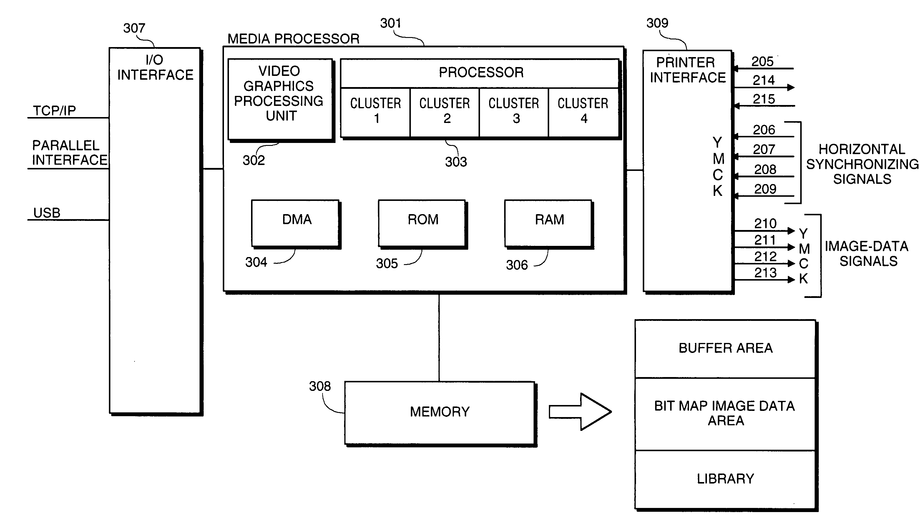
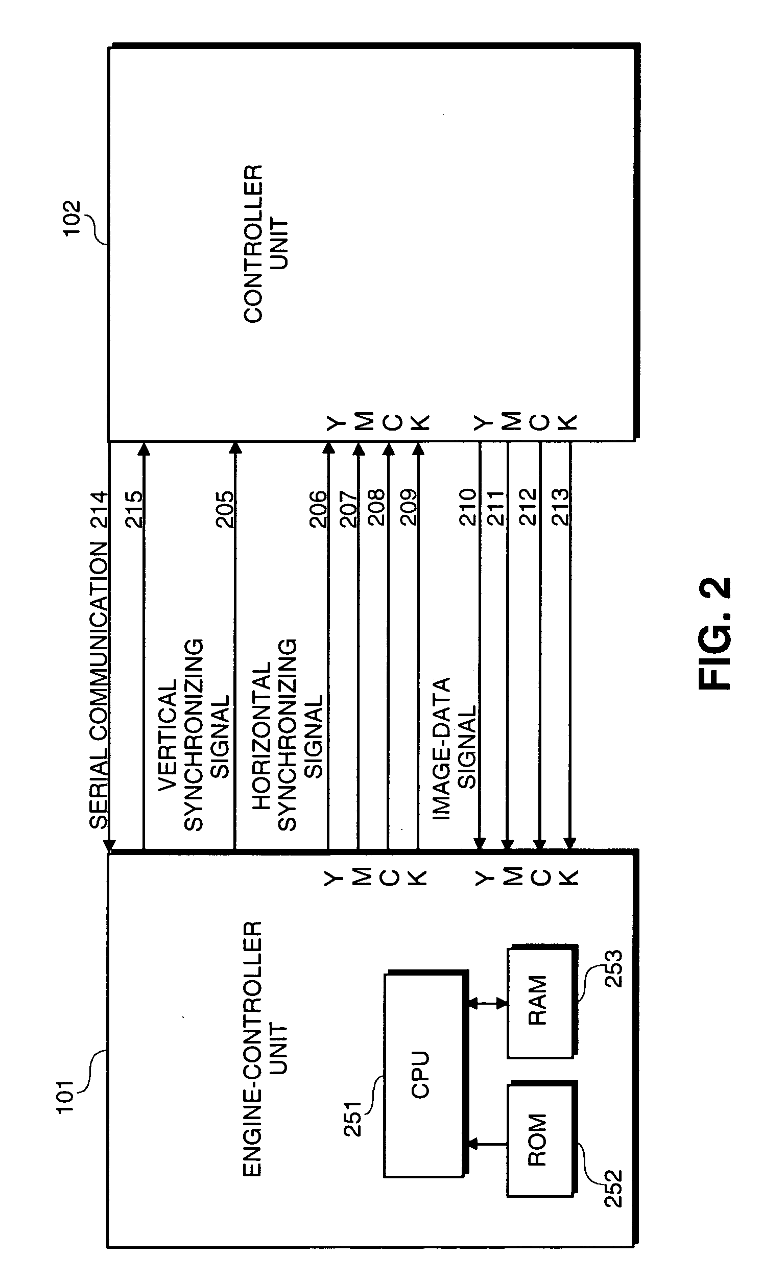
[0027]FIG. 2 shows signal lines to be used for transmitting and / or receiving various types of control signals and data between the engine-controller unit 101 and the controller unit 102 of the

[0028]The symbol 205 denotes a vertical synchronizing signal line for transmitting vertical synchronizing signals from the engine-controller unit 101 to the controller unit 102. The symbol 206 denotes a Y vertical synchronizing signal line for transmitting vertical synchronizing signals for yellow colors from the engine-controller unit 101 to the controller unit 102. The symbol 208 denotes a C vertical synchronizing signal line for transmitting vertical synchronizing signals for cyan colors from the engine-controller unit 101 to the controller unit 102. The symbol 209 denotes a K vertical synchronizing signal line for transmitting vertical synchronizing signals for black colors from the engine-controller unit 101 to the controller unit 102.

[0029]The symbol 210 denotes a Y image-data signal line...

second embodiment

[0097]As illustrated in FIG. 2 with the above-described embodiment, one vertical synchronizing signal line is used as a vertical synchronizing signal line from the engine-controller unit 101 to the controller unit 102. Here, following the input of reference vertical synchronizing signal and output of the yellow image data, the controller 102 sequentially outputs the magenta image data, cyan image data, and black image data, after passage of a certain amount of time. However, the configuration may be arranged so as to be such as that of a

[0098]With the second embodiment, color deviation amount measurement is performed beforehand at the engine-controller unit, the time difference in the image data input timing where the color deviation amount is minimal is calculated, and the time difference in the image data input timing is communicated to the controller unit via serial communication.

[0099]FIG. 17 shows signal lines to be used for transmitting and / or receiving various types of contro...


PUM


Abstract

An image processing method and system is provided wherein a plurality of processors perform a conversion process from a page description language format of data into raster image data, and a printing engine which continuously receives color image data having at least three color components in page unit and prints the at least three color components of color image data on a recording medium in parallel at a constant speed. A page description language format of data is received that includes at least two of the at least three color components as at least an object constituting the page description format data, the page description language format of data is analyzed and, based on the analysis, each color component data of the object in the received data is assigned to each processor such that the plurality of processors perform the conversion processes of the at least two of the at least three color components in parallel thereby producing raster image data of each color component from the plurality of processors to the printing engine in parallel.

Description

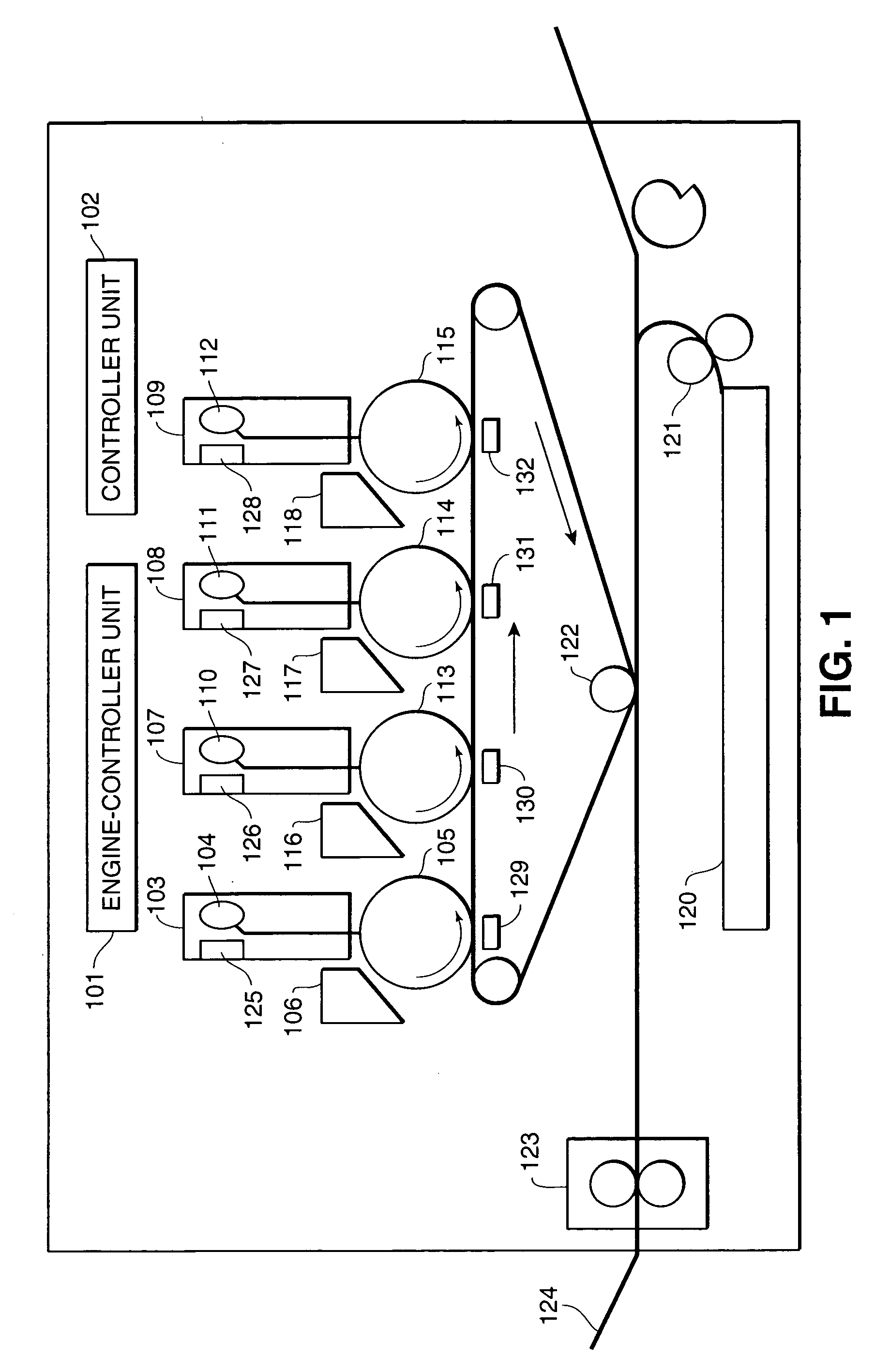
BACKGROUND OF THE INVENTION[0001]1. Field of the Invention[0002]The present invention relates to a printing system including a plurality of processors performing a conversion process from a page description language format of data into raster image data, and a printing engine which continuously receives color image data having at least three color components in page unit and prints the at least three color components of color image data on a recording medium in parallel at a constant speed.[0003]2. Description of the Related Art[0004]Ink-jet and electro-photography color printers are becoming commonplace in recent years. Particularly, with electro-photography color laser printers, photosensitive drums are provided for each of the four colors of cyan, magenta, yellow, and black, color image data (color image data of the four colors, CMYK) is received from a host computer in increments of pages, and the color image data of the four colors is recorded on recording sheets almost simulta...

Claims


Application Information

Patent Timeline
Patent Type & Authority Patents(United States)
IPC IPC(8): H04N1/40B41J5/30G06F3/12G06K15/02G06T1/20
CPCG06K15/02G06K15/1857H04N1/46G06K2215/0094
Inventor TANAHASHI, JUNICHILIN, DENNY M.YAMAZAKI, FUMIYA
Owner CANON KK
Learn More