
Hydraulic tensioner lifter

a technology of hydraulic tensioner and lifter, which is applied in the direction of belt/chain/gearing, mechanical equipment, belt/chain/gearing, etc., can solve the problems of long filling time, large number of steps, and long filling time until the high oil pressure chamber is filled with oil after oil leakage in the oil chamber, so as to reduce the filling time of oil pressure

Inactive Publication Date: 2006-07-04
HONDA MOTOR CO LTD
View PDF21 Cites 41 Cited by
  • Summary
  • Abstract
  • Description
  • Claims
  • Application Information

AI Technical Summary

Benefits of technology

[0013]The present invention has been made in view of such circumstances as described above, and it is an object of the present invention to provide a hydraulic tensioner lifter which can reduce the filling time of oil pressure into an oil chamber which is in a state wherein air is present therein and can sufficiently exhibit a vibration-damping function.

Problems solved by technology

Therefore, the filling time becomes long.
However, in the prior art described above, since the plunger spring is disposed between the bottom portion of the accommodation hole and the plunger in the proximity of the end face of the orifice member adjacent the oil chamber, as the volume of the high oil pressure chamber increases, the filling time until the high oil pressure chamber is filled with oil after oil in the oil chamber leaks becomes long.
Therefore, a great number of steps for assembly of the mechanism for discharging oil to the outside of the tensioner are required.
Therefore, a large size is required for the plunger and hence for the tensioner.

Method used


Image

  • Hydraulic tensioner lifter
  • Hydraulic tensioner lifter
  • Hydraulic tensioner lifter

Examples


Embodiment Construction

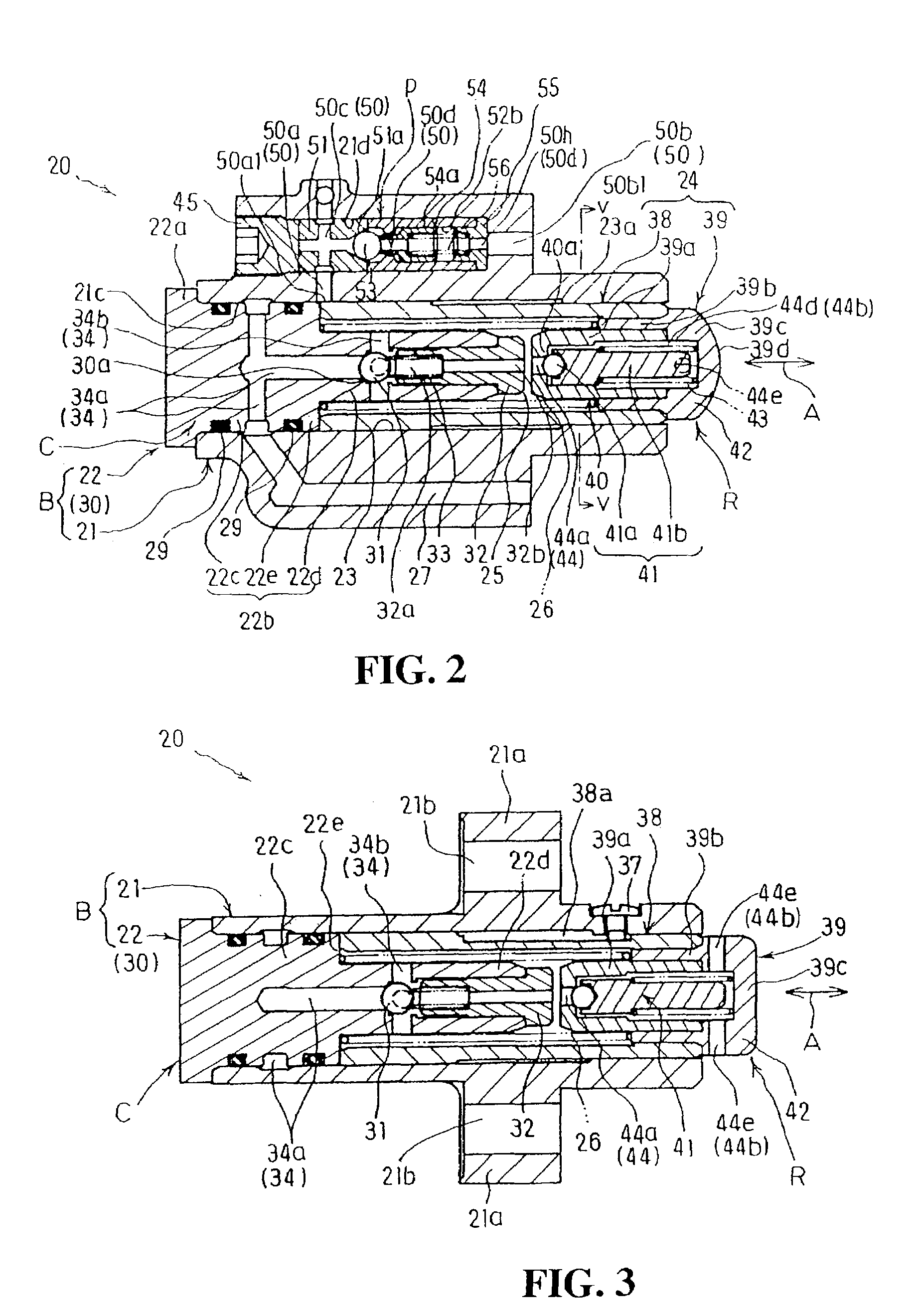
[0065]In the following, embodiments of the present invention are described with reference to FIGS. 1 to 9.

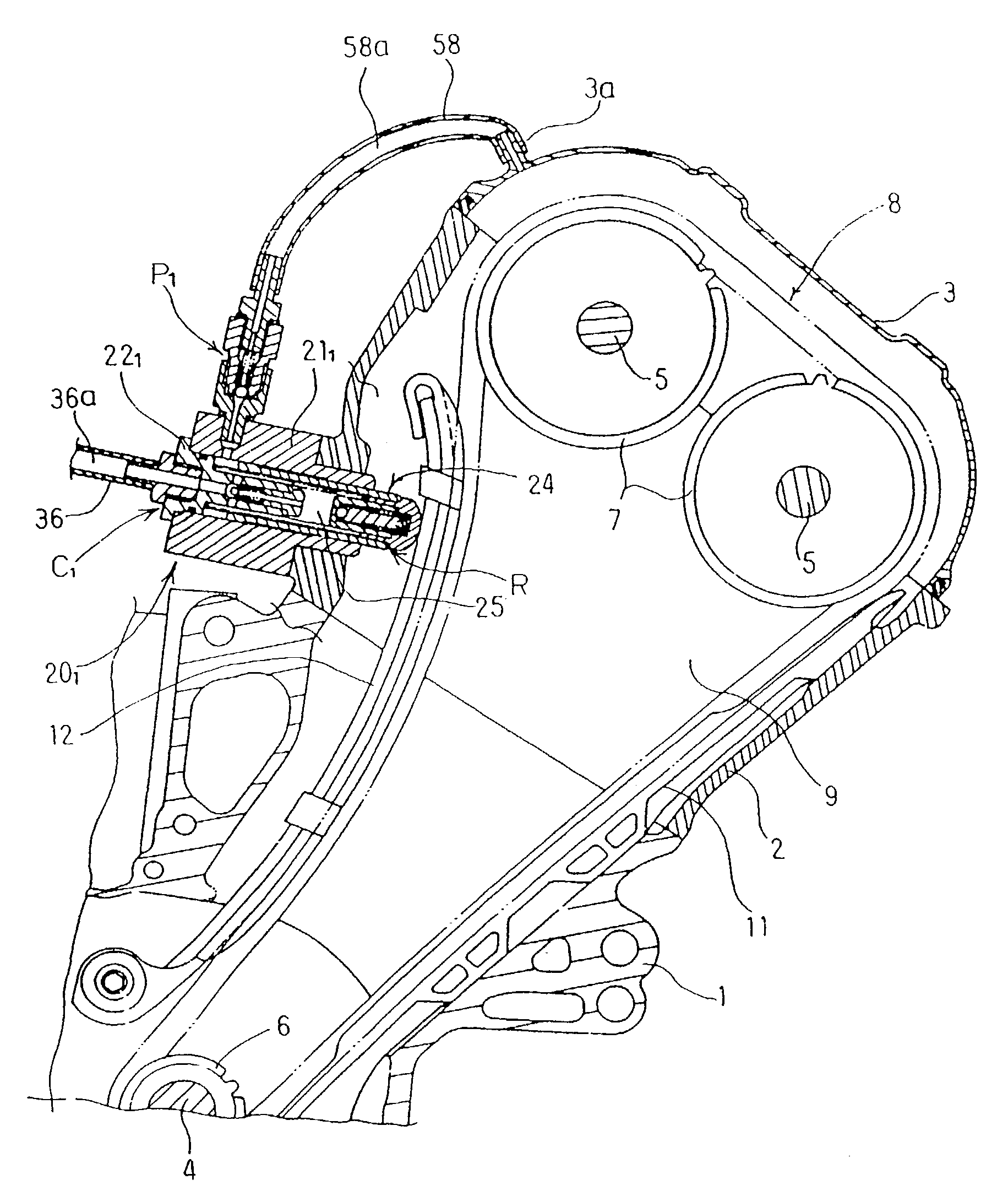
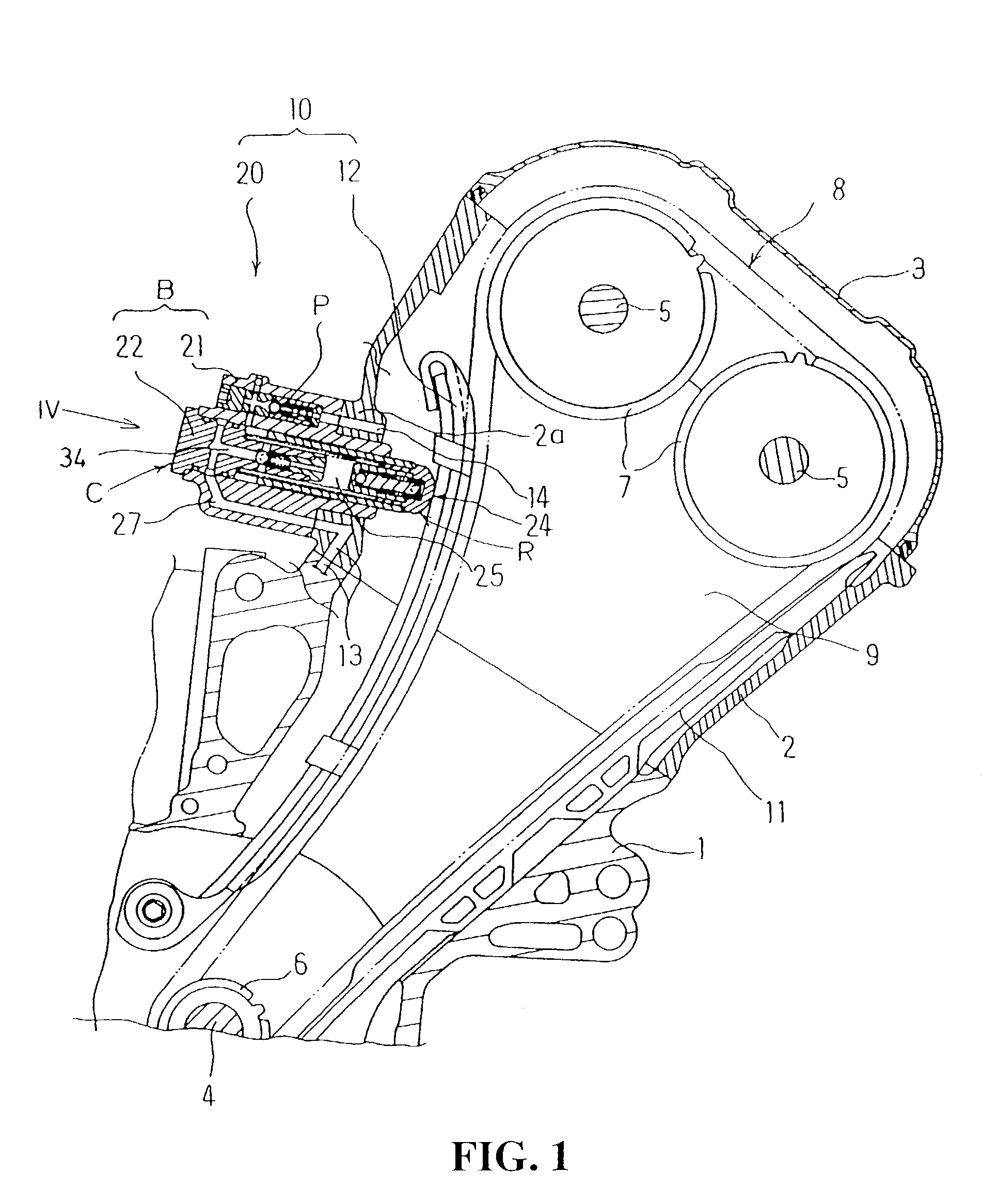
[0066]FIGS. 1 to 6 show a first embodiment of the present invention. FIG. 1 is a sectional view of essential part of an internal combustion engine of the DOHC type wherein a hydraulic tensioner lifter 20 of the present invention is applied to a tensioner for a timing chain 8 which forms a power transmission mechanism for a valve motion. The internal combustion engine includes a cylinder block 1 coupled to an upper end of a crankcase (not shown) and having a cylinder that has a cylinder axis inclined with respect to a horizontal plane, and a cylinder head 2 with a head cover 3 placed in this order on the cylinder block 1.

[0067]In a crank chamber defined by the crankcase and the cylinder block 1, a crankshaft 4 is supported for rotation on a main bearing held between the crankcase and the cylinder block 1 with a valve motion chamber defined by the cylinder head 2 and the head cove...


PUM


Abstract

To provide a hydraulic tensioner lifter which can reduce the filling time of oil pressure into an oil chamber which is in a state wherein air is present therein and can sufficiently exhibit a vibration-damping function. A hydraulic tensioner lifter for applying tension to an endless power transmission band of a power transmission mechanism includes a plunger fitted for sliding movement in an accommodation hole of a tensioner body B and cooperating with the tensioner body B to define an oil chamber therebetween. An air-bleeder mechanism is provided for exhausting air in the oil chamber to the outside of the oil chamber. The purge valve P has a check valve function of permitting the exhaustion of the air in the oil chamber to the outside of the oil chamber but blocking admission of air into the oil chamber from the outside of the oil chamber and blocking discharging of the oil pressure in the oil chamber to the outside of the oil chamber. In addition, the volume of oil in the oil chamber may be decreased by a spring guide portion which is accommodated in the inside of the tensioner spring for guiding the tensioner spring.

Description

CROSS-REFERENCE TO RELATED APPLICATIONS[0001]The present nonprovisional application claims priority under 35 USC 119 to Japanese Patent Application No. 2002-091369 and No. 2002-091764 both filed on Mar. 28, 2002 the entire contents thereof is hereby incorporated by reference.BACKGROUND OF THE INVENTION[0002]1. Field of the Invention[0003]The present invention relates to a hydraulic tensioner lifter of a tensioner for applying tension to an endless power transmission band such as a chain or a belt used for a power transmission mechanism, for example, in an internal combustion engine.[0004]2. Description of Background Art[0005]Conventionally, in an internal combustion engine, a hydraulic tensioner lifter is used in order to apply suitable tension to an endless power transmission band used for a power transmission mechanism such as, for example, a chain. In this hydraulic tensioner lifter, an oil chamber is formed between a plunger biased by a tensioner spring for applying tension to a...

Claims


Application Information

Patent Timeline
IPC IPC(8): F16H7/08F16H7/22
CPCF16H7/0836F16H2007/0859F16H2007/0812F16H2007/0806F16H7/08
Inventor EMIZU, OSAMUNIIMURA, RYUTA
Owner HONDA MOTOR CO LTD
Learn More