
Phase change heat sink for use in electrical solenoids and motors

a technology of electrical solenoids and heat sinks, which is applied in the direction of positive displacement liquid engines, lighting and heating apparatus, furnaces, etc., can solve the problems of affecting the performance of devices, increasing the operating temperature, and many materials used in the conductors, insulation and other working parts of these devices. to achieve the effect of reducing the internal temperature of the devi

Inactive Publication Date: 2006-07-04
LOCKHEED MARTIN CORP
View PDF16 Cites 48 Cited by
  • Summary
  • Abstract
  • Description
  • Claims
  • Application Information

AI Technical Summary

Problems solved by technology

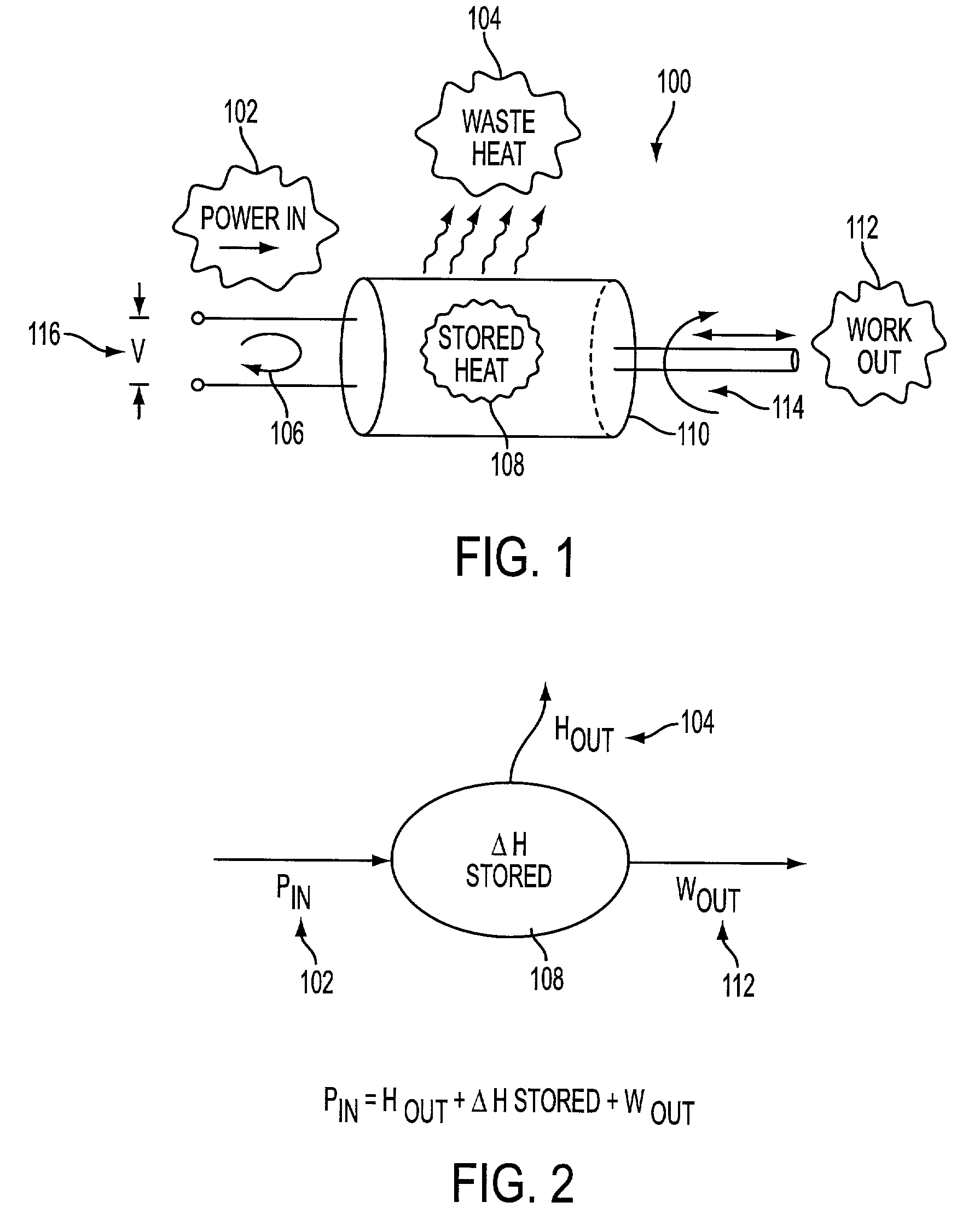
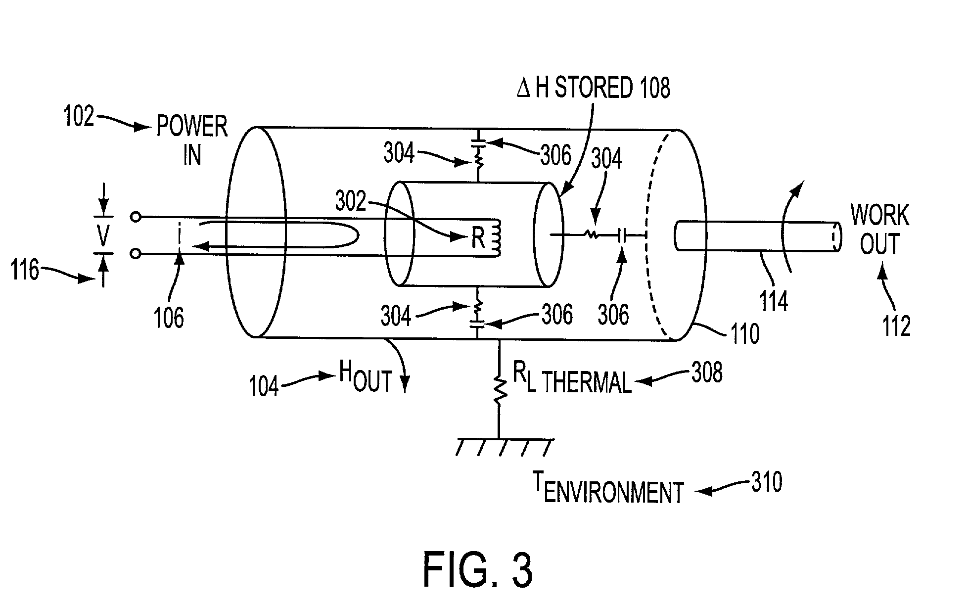
This internal heating is due to electrical power dissipated in resistive heating of magnetic coils, as well as frictional losses, inside the device.
This internal heating is detrimental to device performance in that it produces an increased operating temperature.
Many materials used in the conductors, insulation, and other working parts of these devices are adversely affected by increased temperature.
The performance and reliability of electrical solenoids and motors are diminished by increased internal temperatures caused by waste power dissipation.
In this way, solenoids and motors become less powerful as they heat up due to internal power dissipation leading to unmitigated temperature rise in the electromagnet windings.
Today, this operational performance limitation is normally compensated by over-sizing the motor or solenoid such that it provides excess force or power at the start-up condition, as well as the required force or power at the hot (thermally-degraded) operating conditions.

Method used


Image

  • Phase change heat sink for use in electrical solenoids and motors
  • Phase change heat sink for use in electrical solenoids and motors
  • Phase change heat sink for use in electrical solenoids and motors

Examples


Embodiment Construction

I. Introduction

[0020]In the following description of the preferred embodiments, reference is made to the accompanying drawings which form a part hereof, and in which are shown by way of illustration specific illustrative embodiments in which the invention may be practiced. These embodiments are described in sufficient detail to enable those skilled in the art to practice the invention, and it is to be understood that other embodiments may be utilized and that logical, mechanical and electrical changes may be made without departing from the spirit and scope of the present invention. The following detailed description is, therefore, not to be taken in a limiting sense.

II. Overview of the Invention

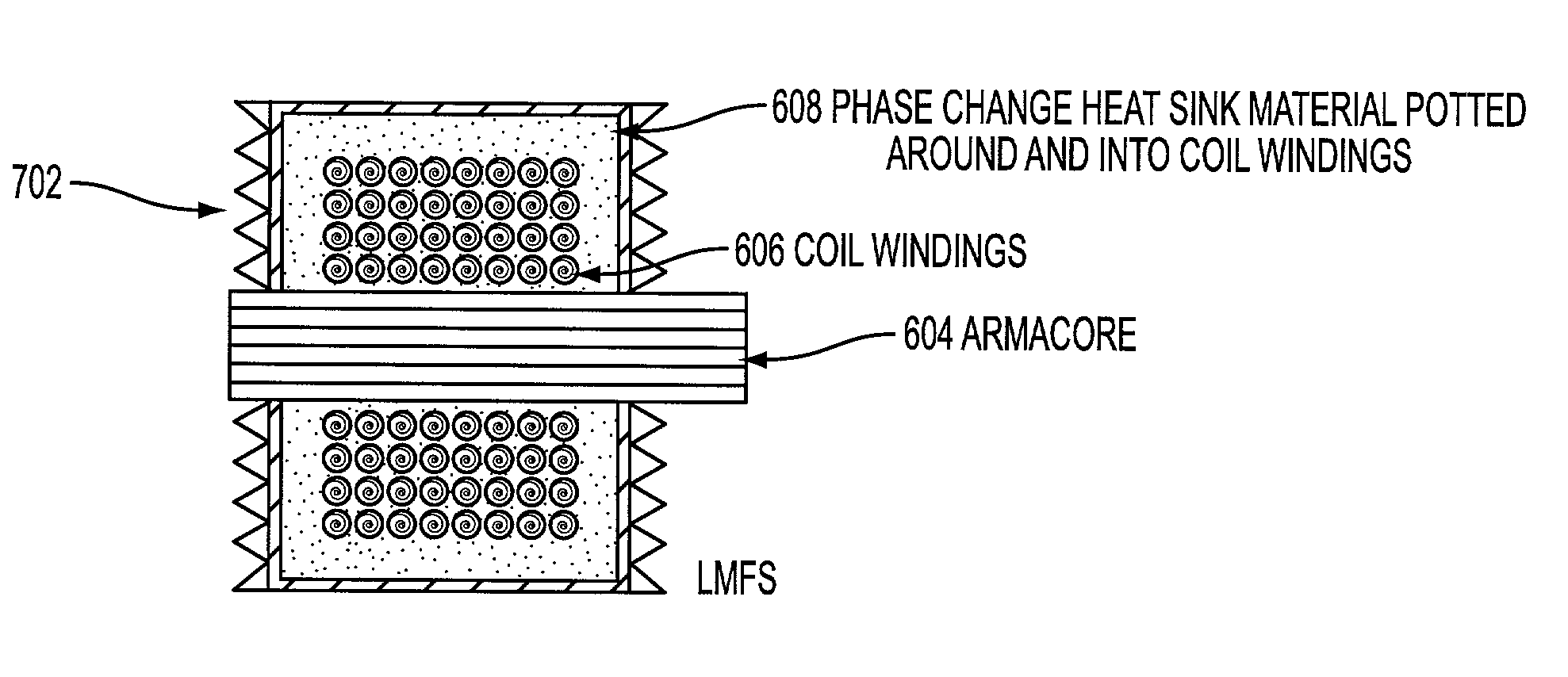
[0021]The present invention places a phase change material (PCM) heat-absorbing material in intimate contact with the structure and / or heat-producing components of the device. This can be achieved by means of potting selected components in the PCM material or by affixing external PCM “packs” ...


PUM

PropertyMeasurementUnit
temperatureaaaaaaaaaa
heataaaaaaaaaa
heat transferaaaaaaaaaa

Abstract

A method, and a system for reducing the internal temperature of an electrical solenoid or motor device involves placing a heat absorbing phase change material (PCM) in intimate contact with the device to reduce the internal temperature of the device. The PCM material reduces the internal operational temperature of the device by undergoing an endothermic phase transition in an operating temperature range of the device. The PCM material transitions between a solid phase and a liquid phase in the internal operational temperature range of the device, or between a liquid phase and a gaseous phase in the internal operational temperature range of the device. The PCM material can be affixed externally to the device. For example, the PCM material is affixed in the form of externally placed pads to the device. The PCM material can also be affixed inside of the device. For example, the PCM material is placed in a potted position around and inside of coil windings of the device, or within an outer structure of the device.

Description

[0001]This application claims the benefit of Provisional application No. 60 / 287,719, filed May 2, 2001.BACKGROUND OF THE INVENTION[0002]1. Field of the Invention[0003]The following invention relates generally to electrical solenoids and motors, and more specifically to reducing internal heating of electrical solenoids and motors during operation.[0004]2. Related Art[0005]Electromagnetic solenoids and motors produce internal heating during operation. This internal heating is due to electrical power dissipated in resistive heating of magnetic coils, as well as frictional losses, inside the device. This internal heating is detrimental to device performance in that it produces an increased operating temperature. Many materials used in the conductors, insulation, and other working parts of these devices are adversely affected by increased temperature. Therefore, maintaining low operating temperatures would simplify design, lower cost, and benefit device life and performance levels.[0006]...

Claims


Application Information

Patent Timeline
Patent Type & Authority Patents(United States)
IPC IPC(8): F28D15/00F28D17/00H01F5/00H02K9/20H02K9/22
CPCH02K9/22H02K9/20F25B21/00F27D17/00
Inventor TOBIAS, LEE A.
Owner LOCKHEED MARTIN CORP
Learn More