Simultaneous forming method of throttle body and throttle valve
a technology of forming method and throttle body, which is applied in the direction of manufacturing tools, machines/engines, and so on, can solve the problems of thickening of the portion of dies forming the gaps between the throttle valve and the throttle body, and achieve the effect of enhancing the durability of the forming di
- Summary
- Abstract
- Description
- Claims
- Application Information
AI Technical Summary
Benefits of technology
Problems solved by technology
Method used
Image
Examples
first embodiment
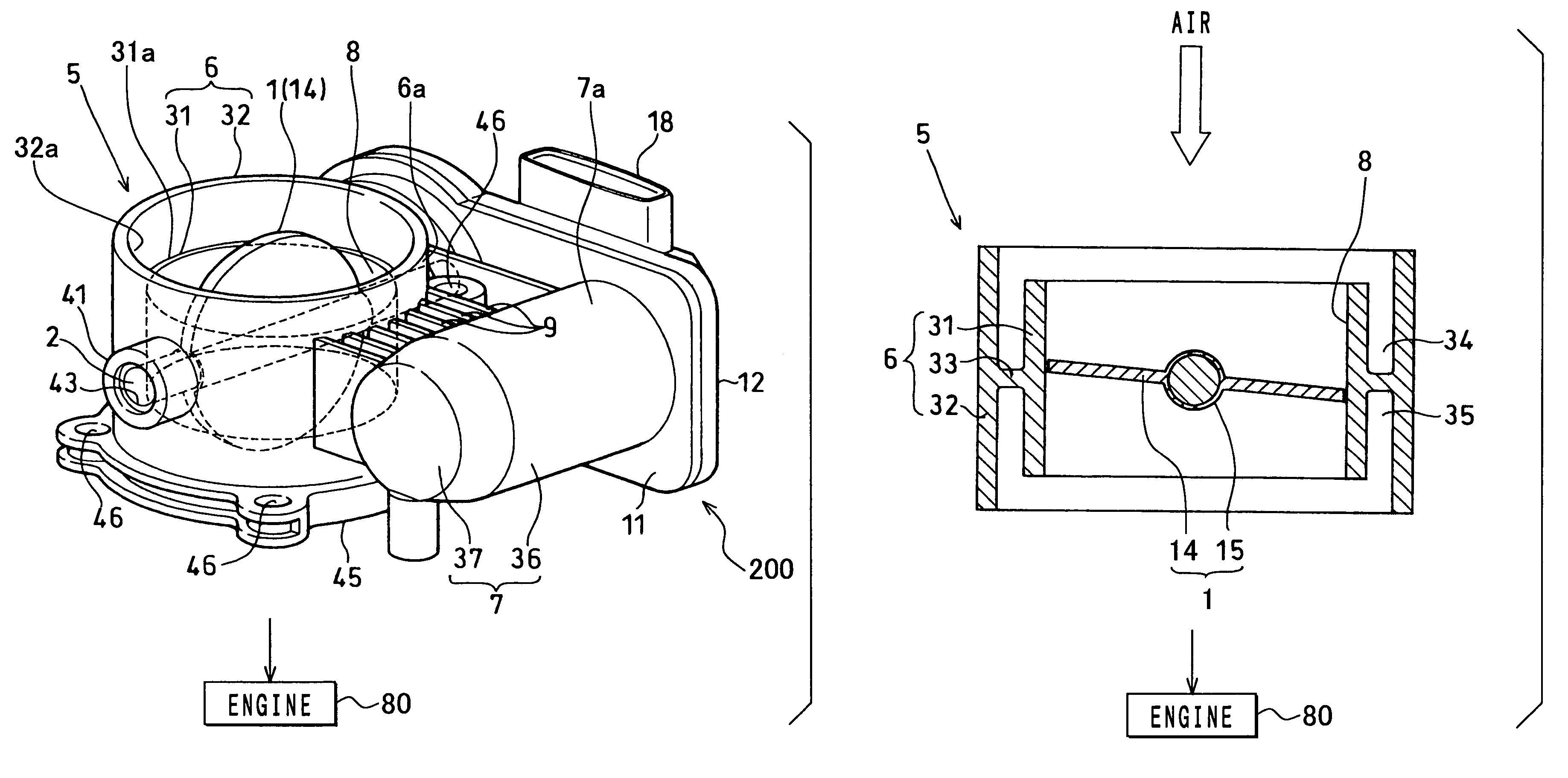
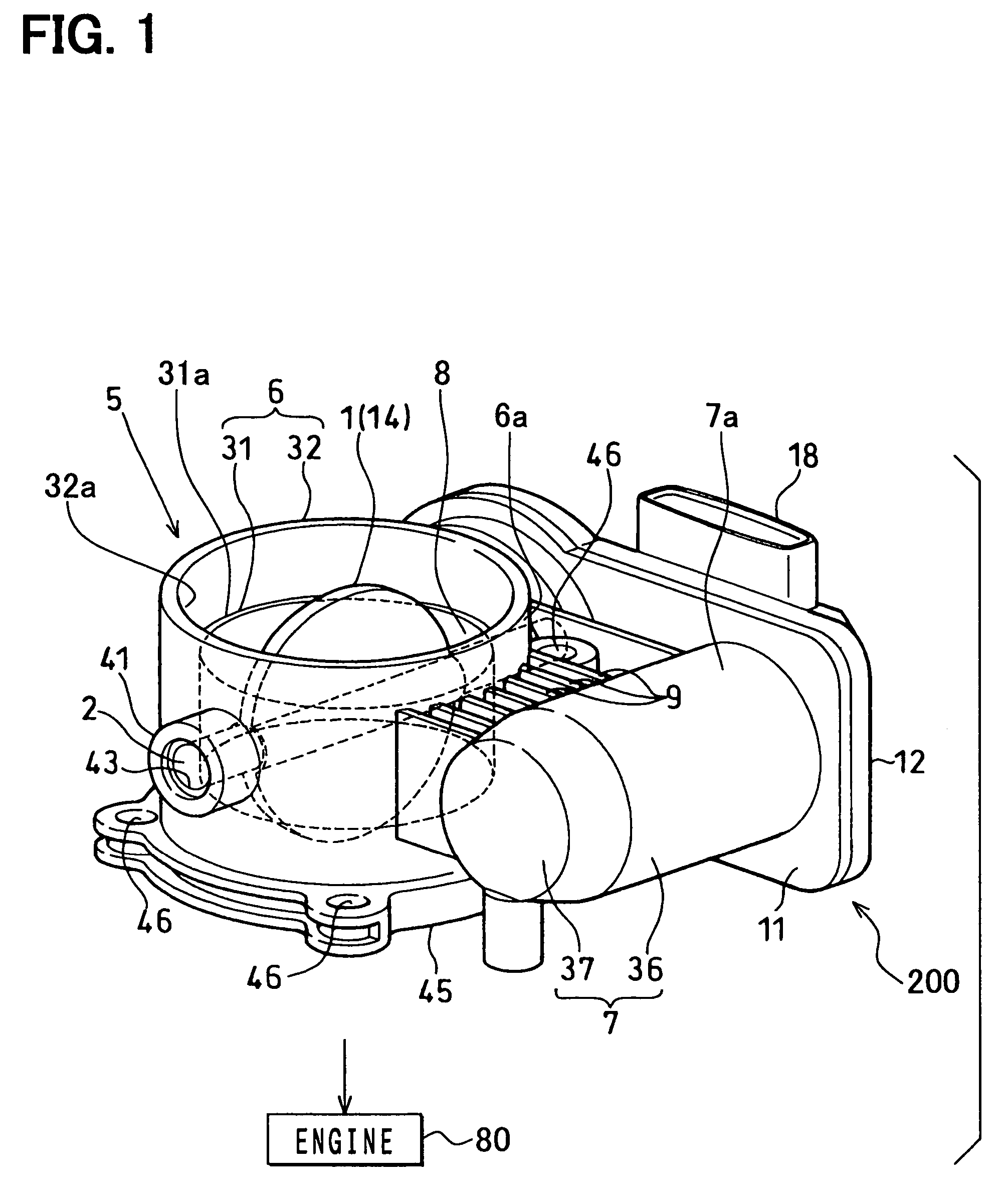
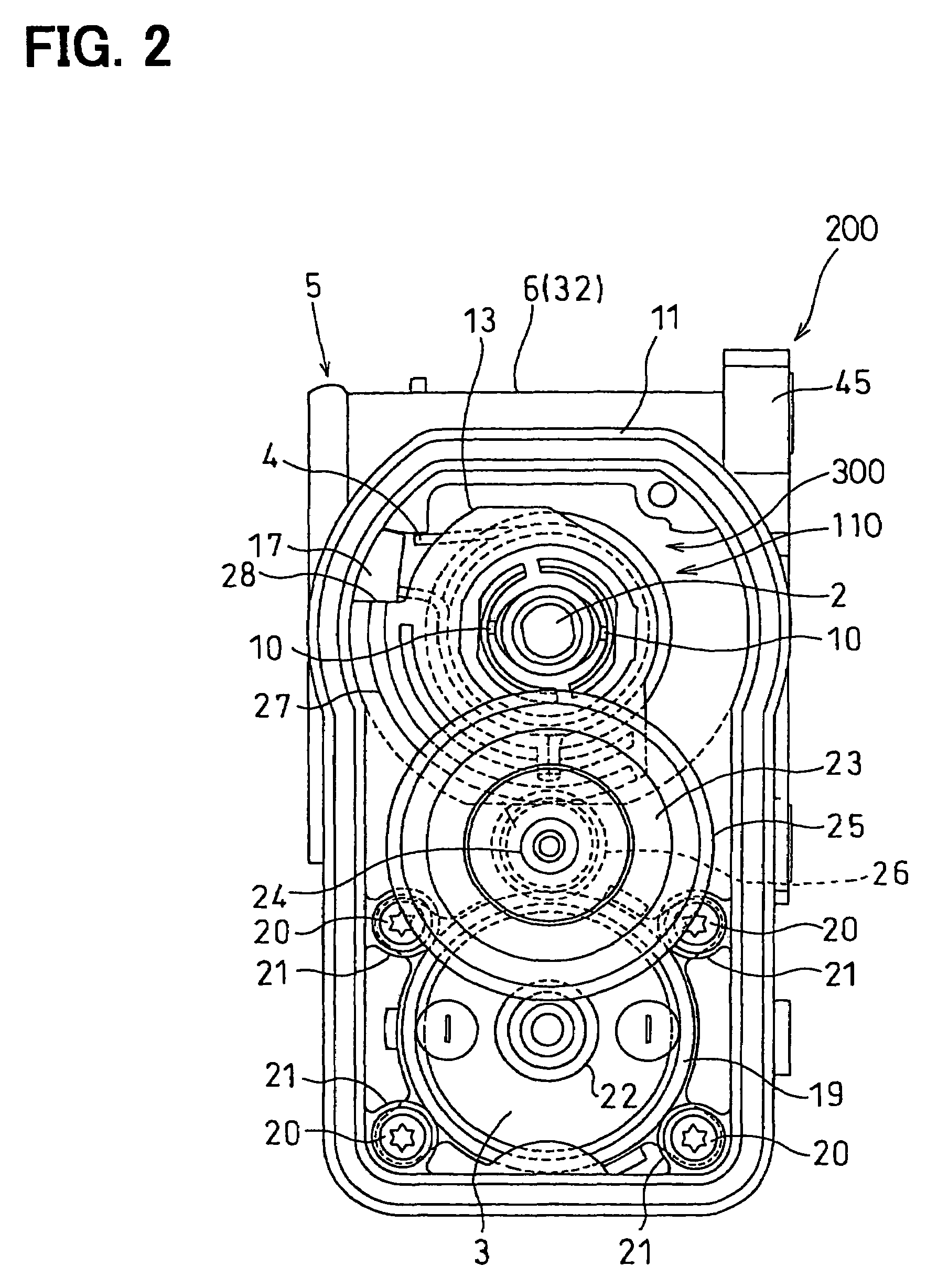
[0035]As shown in FIGS. 1 to 5, an electrically controlled throttle apparatus is constructed with a throttle valve 1, a throttle shaft 2, a driving motor 3, a coil spring 4, reduction gears 300, an actuator case 200, a throttle body 5 and an ECU (electronic control unit). The throttle valve 1 controls an amount of intake air flowing into an internal combustion engine 80. The throttle shaft 2 constructs a shaft part of the throttle valve 1 to be integrally rotated with the throttle valve 1. The driving motor 3 rotates the throttle valve 1 in an open direction, in which the throttle valve 1 is opened to be in a full throttle position (full open position), or a close direction, in which the throttle valve 1 is closed to be in an idling position (full close position). The driving motor 3 serves as an actuator (valve operating means). The coil spring 4 urges the throttle valve 1 in the close direction. The reduction gears (power transmission unit) 300 transmit rotation power of the drivi...
second embodiment
[0074]As shown in FIG. 6, the electrically controlled throttle apparatus in the second embodiment has a coil spring 4 constructed with a first spring part (return spring) 51 and a second spring part (default spring) 52. The return spring 51 serves as a returner spring and the default spring 52 serves as an opener spring. The return spring 51 and the default spring 52 are integrated into one coil spring (valve forcing means) 4 that urges a throttle valve 1 in the close direction and in the open direction of the throttle valve 1. The coil spring 4 is arranged between the outer wall 6a of the bore wall part 6, i.e., bottom wall of the gearbox part 11 and a plane of the valve gear 13 that is located on the side of the bore wall part 6. A connecting member between the return spring 51 and the default spring 52 is bent to be in a substantially U-shape to serve as a U-shaped hook part 54 supported by a middle stopper member 53. Both sides of the coil spring 4 are wound in different directi...
third embodiment
[0080]In the first example shown in FIG. 9, the throttle valve 1 and the throttle body 5 are simultaneously molded in the same molding dies, such that the throttle valve 1, which is in its full close position, is assembled in the bore wall part 6 of the throttle body 5. The gap, which is formed between the cylindrical inner periphery 8 of the bore inner pipe 31 of the throttle body 5 and the outer circumferential periphery of the throttle valve 1, is maintained in a predetermined dimension using the molding die, so that airtightness property can be obtained when the throttle valve 1 is in its full close position.
[0081]However, in the first example shown in FIGS. 10A, 10B, a gap, which is formed between the cylindrical inner periphery 8 of the bore inner pipe 31 of the throttle body 5 and the throttle valve 1, has to be formed over the outer circumferential periphery of the throttle valve 1. Therefore, the molding dies need a thin portion over a large area of the outer circumferentia...
PUM
| Property | Measurement | Unit |
|---|---|---|
| rotation angle | aaaaa | aaaaa |
| rotation angle | aaaaa | aaaaa |
| rotation angle | aaaaa | aaaaa |
Abstract
Description
Claims
Application Information
 - R&D
- Intellectual Property
- Life Sciences
- Materials
- Tech Scout
- Unparalleled Data Quality
- Higher Quality Content
- 60% Fewer Hallucinations
Browse by: Latest US Patents, China's latest patents, Technical Efficacy Thesaurus, Application Domain, Technology Topic, Popular Technical Reports.
© 2025 PatSnap. All rights reserved.Legal|Privacy policy|Modern Slavery Act Transparency Statement|Sitemap|About US| Contact US: help@patsnap.com


