
System and method for improved uplink signal detection and reduced uplink signal power

a technology of uplink signal and system, applied in the field of packet transmission in a network, can solve the problems of node b detection performance not good, extra ul interference is generated, etc., and achieve the effect of reducing the amount that a network node must offset its ack/nack decision threshold, improving uplink signal detection, and reducing the required ack power

Active Publication Date: 2006-06-27
CONVERSANT WIRELESS LICENSING LTD
View PDF15 Cites 52 Cited by
  • Summary
  • Abstract
  • Description
  • Claims
  • Application Information

AI Technical Summary

Benefits of technology

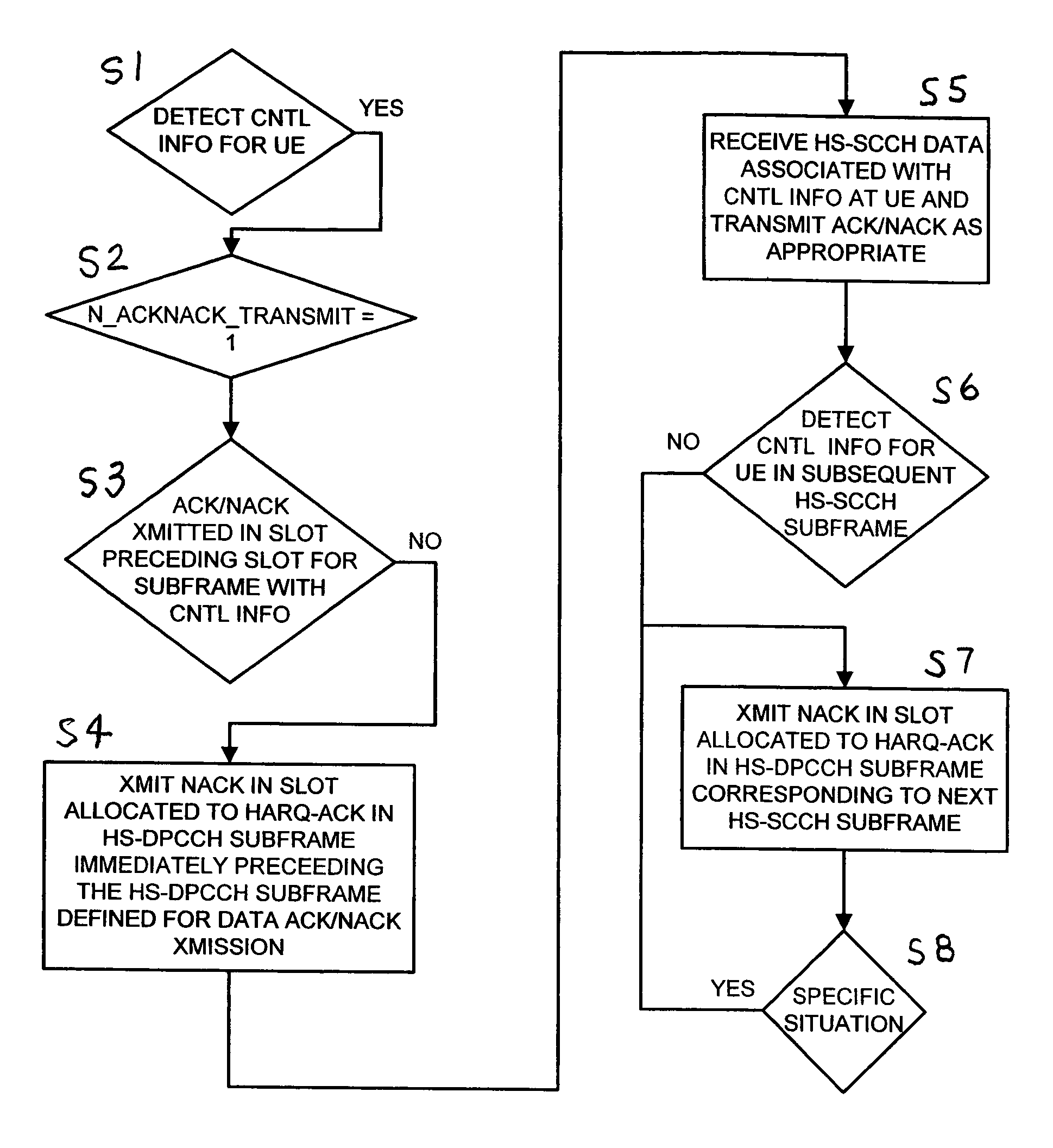
[0007]System and methods for improved uplink signal detection where when a mobile device detects signaling indicating the presence of a packet for that mobile device from a network node, the mobile device may transmit one or more NACKs in a sub-frame before the one in which the mobile device would transmit the normal ACK / NACK for the packet. Additionally, the mobile device may transmit one or more NACKs in the sub-frame immediately following the normal ACK / NACK for a packet (unless a packet was transmitted in the immediately following sub-frame and successfully decoded by the mobile device, in which case an ACK would obviously be transmitted). Therefore, extra uplink (UL) interference is eliminated. Moreover, the amount that a network node must offset its ACK / NACK decision threshold is significantly reduced. This results in a reduction of required ACK power by a mobile device.

Problems solved by technology

However, this method is disadvantageous in that extra UL interference is generated if no HS-DSCH packets are transmitted while the timer is running.
Node B detection performance will not be good if there is need to separately detect ACK, NACK, and also DTX state.

Method used


Image

  • System and method for improved uplink signal detection and reduced uplink signal power
  • System and method for improved uplink signal detection and reduced uplink signal power
  • System and method for improved uplink signal detection and reduced uplink signal power

Examples


Embodiment Construction

[0017]The particulars shown herein are by way of example and for purposes of illustrative discussion of the embodiments of the present invention. The description taken with the drawings make it apparent to those skilled in the art how the present invention may be embodied in practice.

[0018]Further, arrangements may be shown in block diagram form in order to avoid obscuring the invention, and also in view of the fact that specifics with respect to implementation of such block diagram arrangements is highly dependent upon the platform within which the present invention is to be implemented, i.e., specifics should be well within purview of one skilled in the art. Where specific details (e.g., circuits, flowcharts) are set forth in order to describe example embodiments of the invention, it should be apparent to one skilled in the art that the invention can be practiced without these specific details. Finally, it should be apparent that any combination of hard-wired circuitry and softwar...


PUM


Abstract

System and methods for improved uplink signal detection where when a mobile device detects signaling indicating the presence of a packet for that mobile device from a network node, the mobile device may transmit one or more NACKs in a sub-frame before the one in which the mobile device would transmit the normal ACK / NACK for the packet. Additionally, the mobile device may transmit one or more NACKs in the sub-frame immediately following the normal ACK / NACK for a packet (unless a packet was transmitted in the immediately following sub-frame and successfully decoded by the mobile device, in which case an ACK would obviously be transmitted). Therefore, extra uplink (UL) interference is eliminated. Moreover, the amount that a network node must offset its ACK / NACK decision threshold is significantly reduced. This results in a reduction of required ACK power by a mobile device.

Description

[0001]The present application claims priority to U.S. Provisional Patent Application Ser. No. 60 / 456,256 filed Feb. 13, 2003, the entire contents therein being incorporated by reference herein in its entirety.BACKGROUND[0002]1. Field of the Invention[0003]This invention relates to packet transmission in a network, and more specifically to NACK repetition in uplink (UL) packet transmission in a Universal Mobile Telecommunication System (UMTS) for improved uplink signal detection and reduced uplink signal power.[0004]2. Background Information[0005]Currently, the User Equipment (UE), e.g., mobile device, will use discontinuous transmission (DTX) in the acknowledge / negative acknowledge (ACK / NACK) field on the high-speed dedicated physical control channel (HS-DPCCH) if the UE fails to detect correctly the signaling on the high-speed shared control channel (HS-SCCH). The Node B (network device) must offset its ACK / NACK decision threshold so as to avoid erroneously detecting this DTX as an...

Claims


Application Information

Patent Timeline
IPC IPC(8): H04B7/00H04Q7/20G01SH04B7/005H04L1/16H04W52/28
CPCH04L1/0081H04W52/286H04L1/1607H04L1/08Y02B60/50
Inventor HAKKINEN, HANNUTOSKALA, ANTTI
Owner CONVERSANT WIRELESS LICENSING LTD
Learn More