Remote power recharge for electronic equipment

a technology of electronic equipment and remote transmission, which is applied in the direction of electrically long antennas, secondary cells, flow mixers, etc., can solve the problems of reducing the capability of laser beams when transmitting from space to the surface of the earth, and leaving without sufficient power to use portable electronics

Inactive Publication Date: 2006-06-27
PARISE RONALD J
View PDF4 Cites 489 Cited by
  • Summary
  • Abstract
  • Description
  • Claims
  • Application Information

AI Technical Summary

Benefits of technology

[0018]Another object of the invention is to provide a new and improved wireless (conductorless) power

Problems solved by technology

Many simply forget to connect the equipment to the charger and are left without sufficient power to use their portable electronics.
Transmitting from space to t

Method used


Image

  • Remote power recharge for electronic equipment
  • Remote power recharge for electronic equipment
  • Remote power recharge for electronic equipment

Examples


Embodiment Construction

[0062]The disclosures of U.S. patent application Ser. No. 09 / 648,951, filed Aug. 25, 2000, U.S. patent application Ser. No. 09 / 436,921 filed Nov. 8, 1999, and U.S. patent application Ser. No. 08 / 934,270 filed Sep. 16, 1997, now U.S. Pat. No. 5,982,139, are incorporated by reference herein.

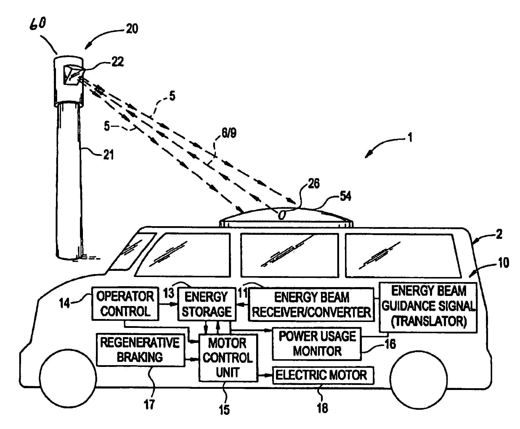
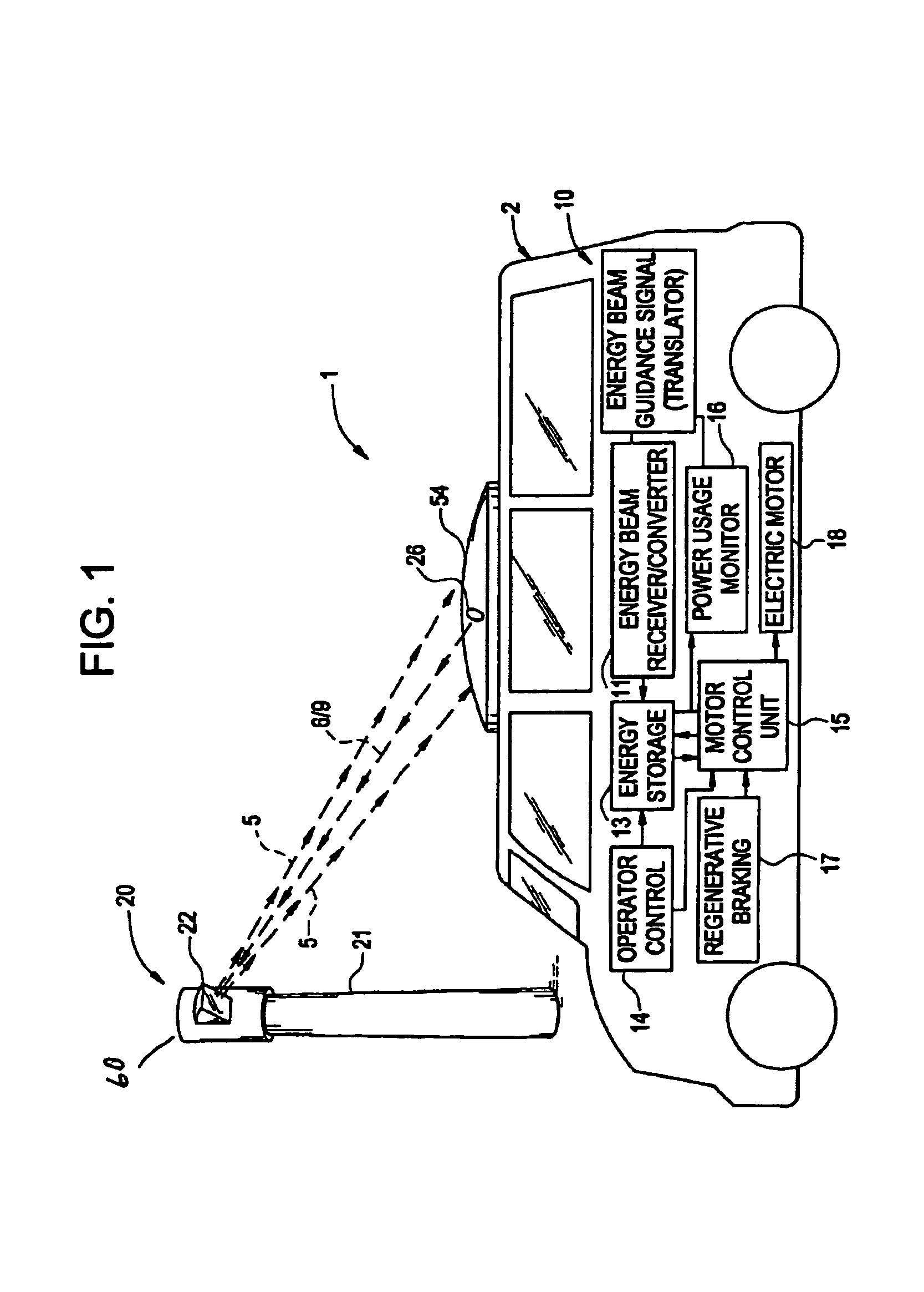
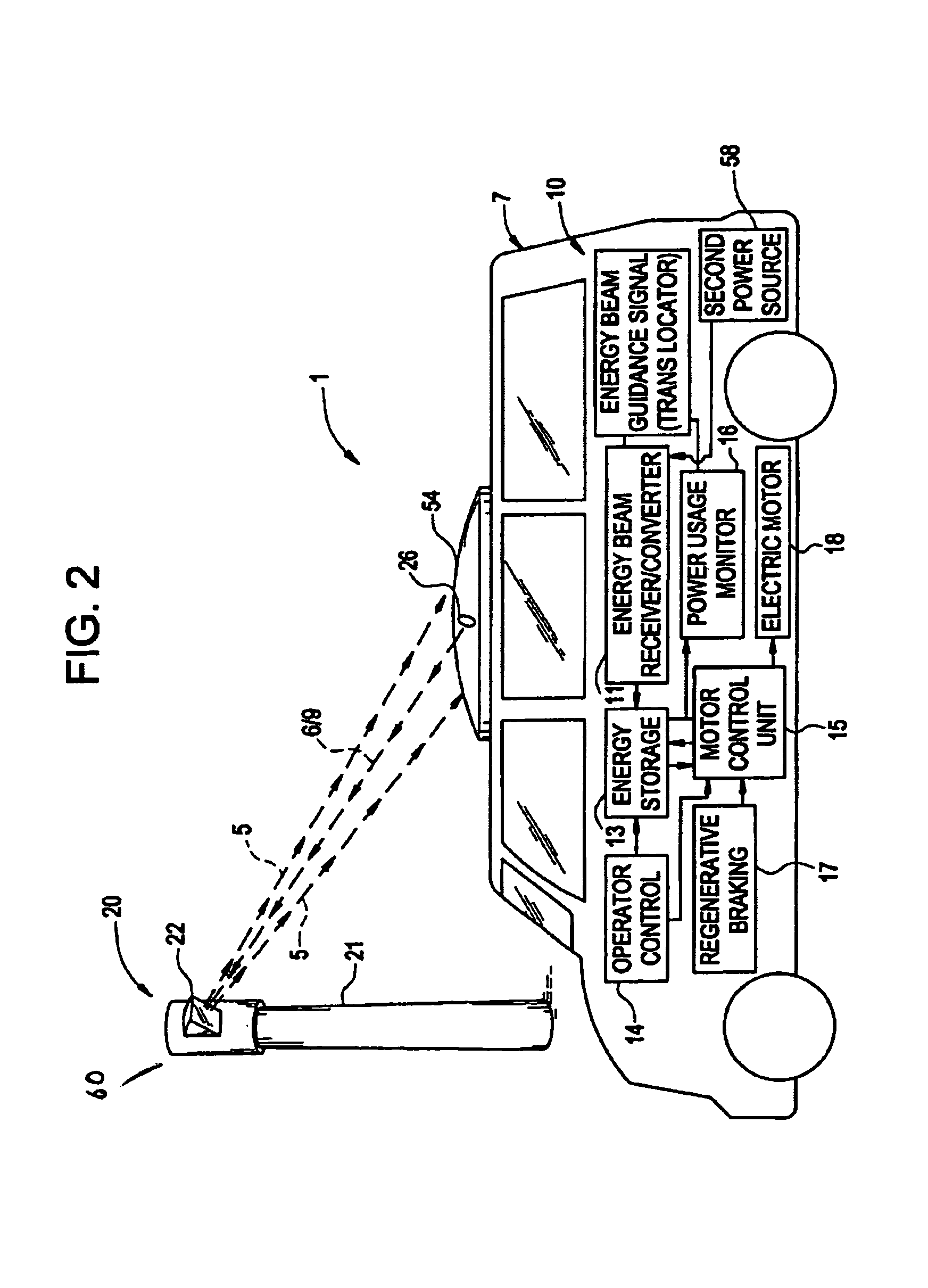
[0063]With reference to the drawings wherein like numerals represent like components or structures throughout the figures, a remote power system according to aspects of the present invention is generally represented by the numeral 1. As shown in functional block diagrams FIGS. 11A–11C, the remote power system comprises a power transmission unit (PTU) 20 and a power receiving system (PRS) 44. A remote power system according to aspects of the present invention is a flexible multi-use system whose basic components and functions may be supplemented with additional features appropriate for a particular intended use. The remote power system will be broadly described in the context of power delivery to an...


PUM

PropertyMeasurementUnit
Poweraaaaaaaaaa
Transmissionaaaaaaaaaa
Frequencyaaaaaaaaaa

Abstract

A conductorless charging and power system for electronic appliances and method for communicating power to a power receiver employing wireless energy transmission are disclosed. The remote charging system includes a power transmission unit, which transmits energy as a directional power beam, and a power receiver system that receives the transmitted energy. The power receiver system is preferably incorporated in an appliance and includes an energy receptor capable of receiving the wireless power beam and transferring the energy from the beam to an energy storage device included in the appliance. The power transmission unit receives and tracks a power request signal from the power receiver system to track the power receiver system location during energy transmission. Data streams may be incorporated into the wireless signals of the remote charging system, allowing the remote charging system to function as a communications pathway as well as a power delivery system.

Description

CROSS-REFERENCE TO RELATED APPLICATION[0001]This is a continuation-in-part application of U.S. patent application Ser. No. 09 / 648,951, filed Aug. 25, 2000 now U.S. Pat. No. 6,792,259, which is a continuation of U.S. patent application Ser. No. 09 / 436,291, filed Nov. 8, 1999, now U.S. Pat. No. 6,114,834, which is a continuation of U.S. patent application Ser. No. 08 / 934,270, filed Sep. 19, 1997, now U.S. Pat. No. 5,982,139, which claims the benefit of U.S. Provisional Application No. 60 / 046,027, filed May 9, 1997.BACKGROUND OF THE INVENTION[0002]The present invention relates in general to a wireless power transmission system. One particular aspect of the present invention relates to a remote power transmission system for recharging electronic equipment.[0003]Millions of portable electronic devices are in use today. Each of these devices typically employs a rechargeable battery pack that requires periodic connection to a charger. Many simply forget to connect the equipment to the char...

Claims


Application Information

Patent Timeline
IPC IPC(8): H04Q7/20B01F5/06B01F13/00B29C48/33B29C48/92B60L8/00F01N3/20H01L35/00H01M8/04H01M10/44H01M10/50H02J7/02H02J17/00
CPCB01F5/0614B60L11/002B60L11/1801B60L11/182B60L11/185F01N3/2006H01L35/00H01M8/04007H01M10/443H02J7/025H02J17/00B29C47/92Y02T90/121B01F2215/0039B60L2270/32Y02E60/50Y02T10/7005Y02T90/122Y02T90/128Y02T90/14Y02T90/16Y02T10/26Y02T90/168Y04S30/12B01F13/002Y02T10/7072B60L50/53B60L50/90B60L53/11H02J50/10B60L53/126H02J7/34Y02T10/12Y02T10/70Y02E60/10H02J50/80H02J50/27H02J50/90H02J50/40H02J50/30H02J50/60B01F25/4314B01F33/5011B01F2101/2305H10N10/00Y02T90/12Y02T90/167
Inventor PARISE, RONALD J.
Owner PARISE RONALD J
Why Eureka
Try Eureka