
Piezoelectric device, cellular phone system using the piezoelectric device, and electronic equipment using the piezoelectric device

a piezoelectric device and cellular phone technology, applied in the direction of piezoelectric/electrostrictive/magnetostrictive devices, piezoelectric/electrostriction/magnetostriction machines, impedence networks, etc., can solve the problem of insufficient adhesion strength of the resonator element b>1/b>, difficult to apply a small amount of conductive adhesive to the electrodes, and difficult to effectively inhibit vibration

Inactive Publication Date: 2006-06-27
SEIKO EPSON CORP
View PDF11 Cites 46 Cited by
  • Summary
  • Abstract
  • Description
  • Claims
  • Application Information

AI Technical Summary

Benefits of technology

The present invention provides a piezoelectric device with a resonator element housed in a package. The device includes a base substrate, a framed resonator element adhered to the base substrate, and a lid for hermetically sealing the package. The framed resonator element includes a frame, a base having a predetermined width, a plurality of resonating arms that extend in parallel to each other from the base in one direction, and first and second cutouts. The first cutouts are near the base ends of the resonating arms in the base and are formed to narrow the width of the base. The second cutouts are at the joint between the base and the frame and are formed to narrow the width of the base. The device has a sufficient impact resistance even when reduced in size. The width of the base substrate should be less than 500 μm to avoid short-circuiting. The resonating arms have grooves in which excitation electrodes are formed to excite a current. The invention provides a piezoelectric device that can effectively inhibit vibration leakage and prevent damage from external impact.

Problems solved by technology

Particularly, it is difficult to use the conductive adhesives to adhere the extraction electrodes to the base 10 with the extraction electrodes being electrically separated from the base 10.
In other words, it becomes difficult to apply a small amount of the conductive adhesive to the electrodes separated from each other at minute intervals on the inner surface of the package so as not to short-circuit the electrodes.
Since it is necessary to limit the amount of applied conductive adhesive for preventing the electrodes from being short-circuited, the adhesion strength of the resonator element 1 becomes insufficient.
As a result, when an external impact is applied, the stress is concentrated on the extremely narrow connecting part 7a and, therefore, the connecting part 7a is in danger of being damaged.
Accordingly, it is disadvantageously difficult to form the piezoelectric device having a sufficient impact resistance.
As shown in FIGS. 13(a) and 13(b), the piezoelectric device is adversely and significantly affected in its performance.
However, when the width of the second cutouts exceeds 75% of the width of the base, the stress due to an impact on the frame transmitted to the resonator element body cannot be reduced to a sufficient level.

Method used


Image

  • Piezoelectric device, cellular phone system using the piezoelectric device, and electronic equipment using the piezoelectric device
  • Piezoelectric device, cellular phone system using the piezoelectric device, and electronic equipment using the piezoelectric device
  • Piezoelectric device, cellular phone system using the piezoelectric device, and electronic equipment using the piezoelectric device

Examples


first embodiment

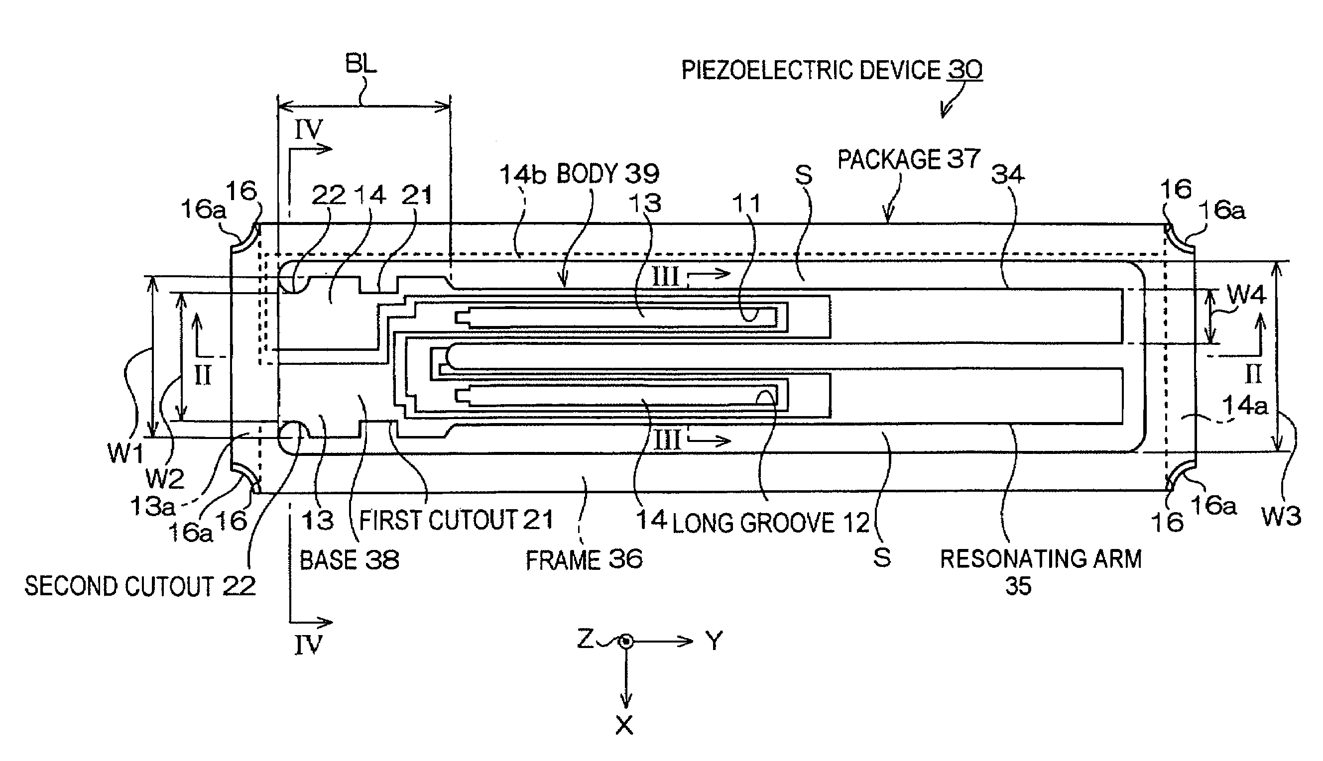
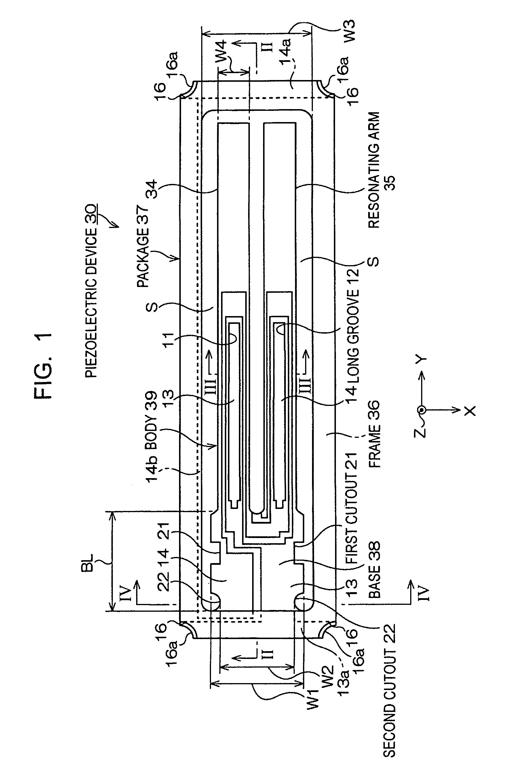
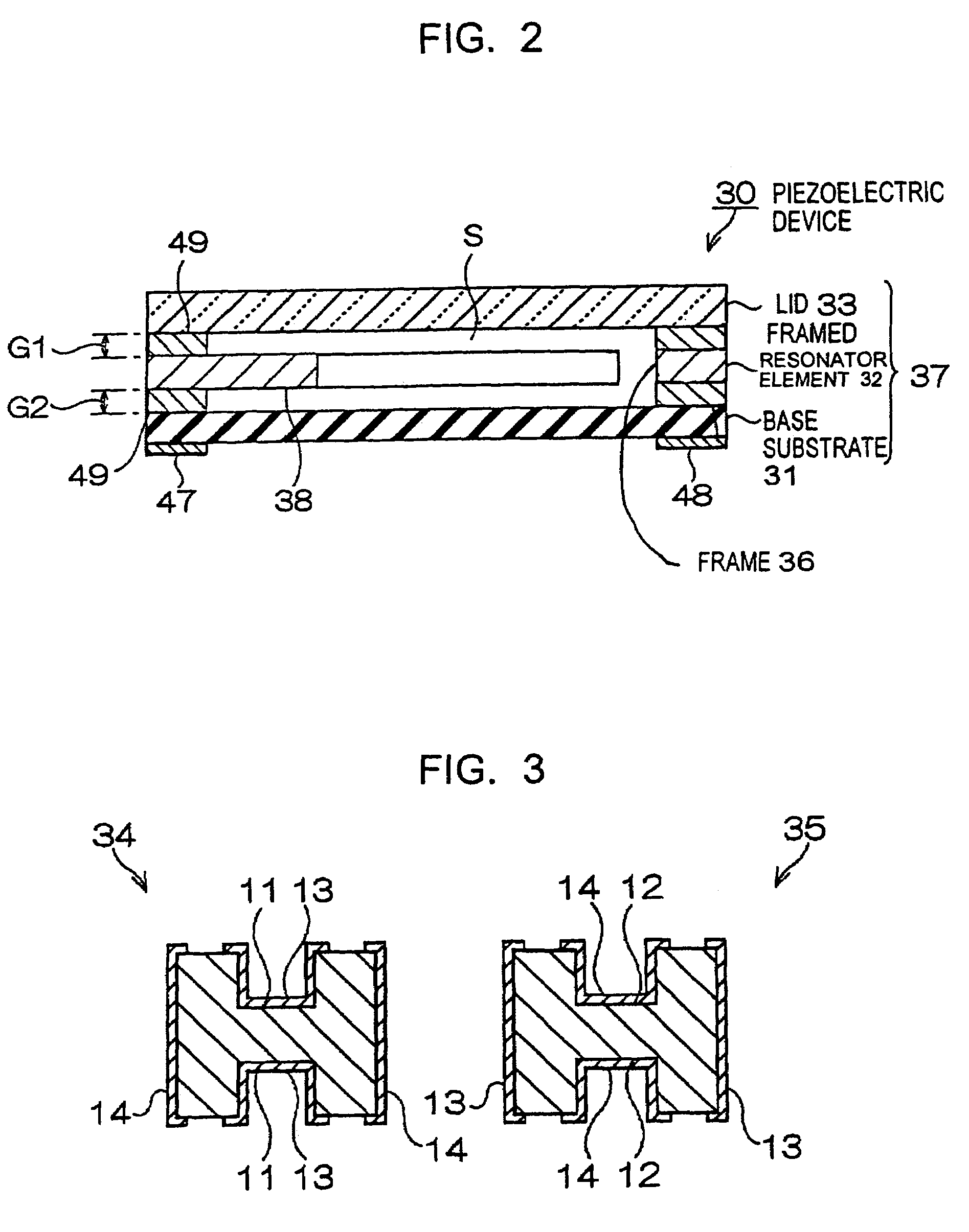
[0050]FIGS. 1 to 3 show a piezoelectric device according to the present invention. FIG. 1 is a schematic plan view of the piezoelectric device, FIG. 2 is a schematic cross-sectional view thereof taken along line II—II in FIG. 1, and FIG. 3 is a sectional end view thereof taken along line III—III in FIG. 1.

[0051]Referring to FIGS. 1 to 3, a piezoelectric device 30 constitutes a piezoelectric transducer. The piezoelectric device 30 has a resonator element housed in a package 37.

[0052]Specifically, the piezoelectric device 30 has a base substrate 31, a framed resonator element 32 that is fixed on the base substrate 31, and a lid 33 that is layered and fixed on the framed resonator element 32.

[0053]In the piezoelectric device 30, the package 37 for hermetically housing the resonator element is structured so as to include the base substrate 31, the frame of the framed resonator element 32, and the lid 33. In other words, layering the lid 33 on the framed resonator element 32 that is laye...

second embodiment

[0078]FIGS. 6 and 7 show a piezoelectric device according to the present invention. FIG. 6 is a schematic plan view of the piezoelectric device and FIG. 7 is a schematic cross-sectional view thereof taken along line VII—VII in FIG. 6.

[0079]The same reference numerals are used in FIGS. 6 and 7 to identify the same components as in the piezoelectric device 30 of the first embodiment. A duplicated description is omitted here and only differences are mainly described.

[0080]A piezoelectric device 60 of the second embodiment is structured so as to house the framed resonator element 32 in the first embodiment in a package 37-1.

[0081]The package 37-1, made of an insulating material, is a rectangular box. For example, a first substrate 51, a second substrate 52, and a third substrate 53 are sequentially layered to form the package 37-1. A through-hole 43 is formed near the center of the package 37-1. The first substrate 51 and the second substrate 52 constitute a base substrate. The through-...

third embodiment

[0087]FIGS. 8 and 9 show a piezoelectric device according to the present invention. FIG. 8 is a schematic plan view of the piezoelectric device and FIG. 9 is a schematic cross-sectional view thereof taken along line IX—IX in FIG. 8.

[0088]The same reference numerals are used in FIGS. 8 and 9 to identify the same components in the piezoelectric device 30 of the first embodiment and the piezoelectric device 60 of the second embodiment. A duplicated description is omitted here and only differences are mainly described.

[0089]A piezoelectric device 70 of the third embodiment is structured so as to house a framed resonator element 72 in the package 37-1, as in the second embodiment.

[0090]The piezoelectric device 70 of the third embodiment differs from the piezoelectric device 60 of the second embodiment in the structure of the framed resonator element 72. A framed resonator element part 36-1 of the framed resonator element 72 is not provided around the resonator element body 39, but is for...


PUM


Abstract

A piezoelectric device includes a base substrate constituting the bottom of the package; a framed resonator element layered on the base substrate; and a lid for hermetically sealing a space within the package, the lid being layered on the framed resonator element. The framed resonator element includes a frame constituting a wall surrounding the space within the package; a base having a predetermined width, which is integrally formed inside the frame; a plurality of resonating arms that extend in parallel to each other from the base in one direction in the frame; first cutouts that are provided near the base ends of the resonating arms in the base; and second cutouts formed at the joint between the base and the frame.

Description

RELATED APPLICATIONS[0001]This application claims priority to Japanese Patent Application No. 2003-338558 filed Sep. 29, 2003 which is hereby expressly incorporated by reference herein in its entirety.BACKGROUND[0002]1. Technical Field[0003]The present invention relates to a piezoelectric device having a resonator element housed in a package, a cellular phone system using the piezoelectric device, and electronic equipment using the piezoelectric device.[0004]2. Background Art[0005]Piezoelectric devices, such as piezoelectric transducers or piezoelectric oscillators, are in widespread use in hard disk drives (HDDs), mobile computers, small computer equipment including IC cards, and mobile communication equipment including cellular phones, automobile telephones, and paging systems.[0006]A known piezoelectric device has, for example, a resonator element shown in FIG. 11 housed in a package (refer to Japanese Unexamined Patent Application Publication No. 2002-261575).[0007]Referring to ...

Claims


Application Information

Patent Timeline
Patent Type & Authority Patents(United States)
IPC IPC(8): H01L41/08H03H9/02H03H9/10H03H9/05H03H9/09H03H9/21H10N30/00
CPCH03H9/21H10N30/00
Inventor TANAYA, HIDEO
Owner SEIKO EPSON CORP
Learn More