
Microfluidic accumulating and proportioning component

a technology of microfluidics and components, applied in the field of microfluidic accumulating and proportioning components, can solve the problems of faulty proportioning, interfering with the proportioning process, and forming bubbles with concomitant liquid losses,

Inactive Publication Date: 2006-06-27
EPPENDORF AG
View PDF7 Cites 9 Cited by
  • Summary
  • Abstract
  • Description
  • Claims
  • Application Information

AI Technical Summary

Benefits of technology

[0018]The capillary cavities in the reservoir already cause a reduction of the pressure the liquid has in the proportioning outlet. The pressure of the liquid is additionally reduced in the proportioning outlet because the reservoir and the displacement chamber are partially disposed at the same level since this diminishes the hydrostatic pressure of the liquid. It is preferred that the capillary cavities and the levels of the reservoir and displacement chamber are designed in such a way that the capillary pressure of the liquid in the reservoir at least corresponds to the hydrostatic pressure of the liquid in the proportioning outlet. The overall pressure of the liquid in the proportioning outlet will then maximally correspond to the ambient pressure such that liquid will not leak out by itself.
[0079]The configuration of the inlet and the proportioning outlet of the displacement chamber is the object of an optimization which is aimed at receiving a maximum liquid volume from the reservoir when the displacement chamber is expanded and avoiding an entry of air through the outlet. When the displacement chamber is compressed the whole liquid volume received should be delivered, if possible, from the proportioning outlet and as little air as possible should be forced back into the reservoir. It is preferred that the liquid is delivered from the proportioning outlet in an open jet. According to an advantageous aspect, the chamber can have an inlet with a throttle valve and / or a proportioning outlet with a nozzle.

Problems solved by technology

The capillary compensation system prevents the formation of bubbles which could appear in the accumulated liquid volume during an acceleration, e.g. during a fall of the reservoir, and could interfere with the proportioning process.
However, a leakage of liquid or formation of bubbles with concomitant liquid losses and faulty proportionings may still occur in the previously described microproportioning system.

Method used


Image

  • Microfluidic accumulating and proportioning component
  • Microfluidic accumulating and proportioning component
  • Microfluidic accumulating and proportioning component

Examples


Embodiment Construction

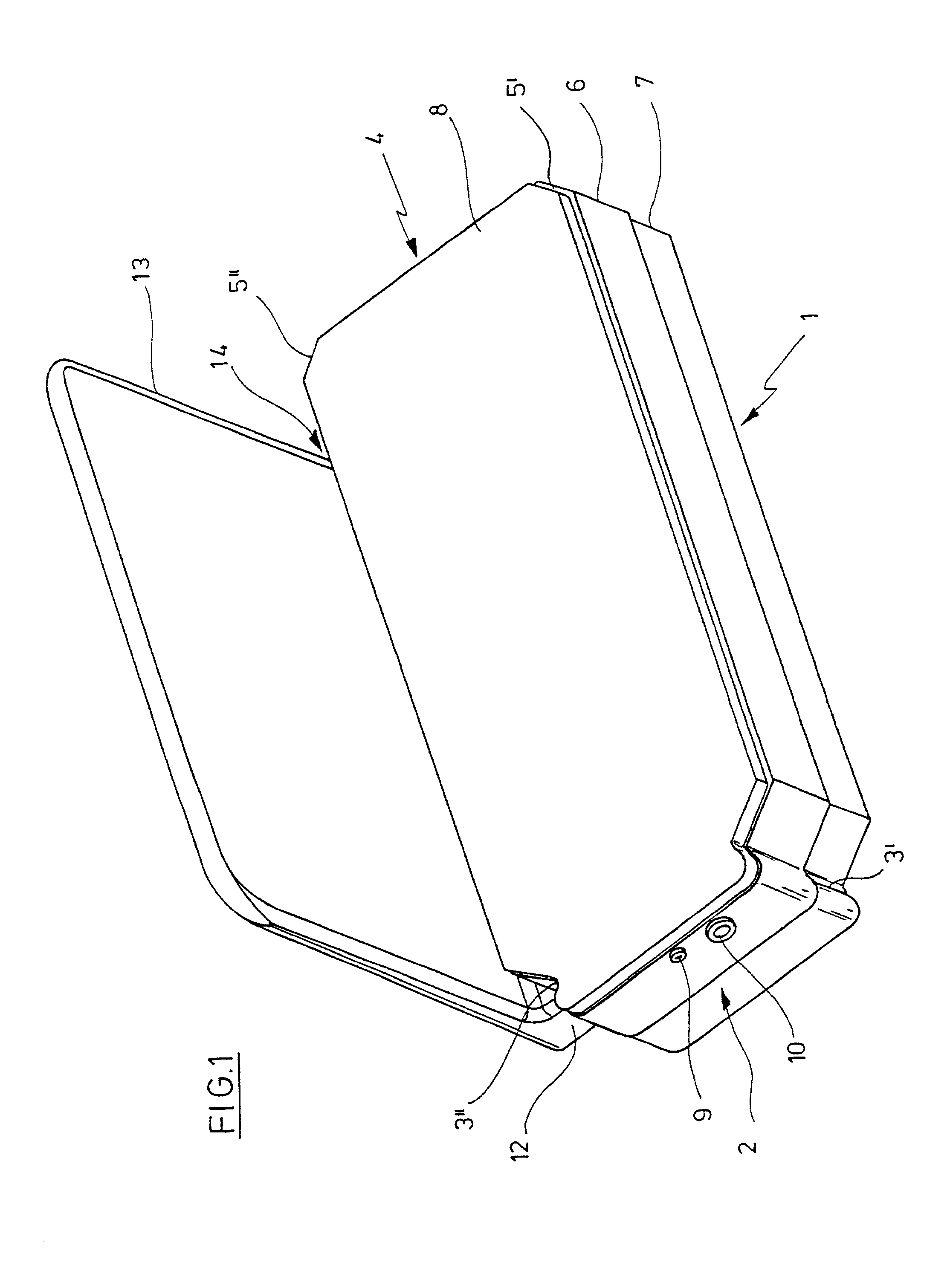
[0094]Referring to FIG. 1, the microfluidic accumulating and proportioning component has a substantially planar body 1 which has a catch contour 3′, 3″ adjacent to one end face 2, which is of a dovetail shape if seen in a plan view, in the narrow sides and which is chamfered on the other end face 4 at 5′, 5″ towards the narrow sides.

[0095]The body 1 is formed from superposed plate-shaped bodies of a substantially complementary outer contour which comprise a basic body 6, a reservoir lid 6, and a diaphragm lid 8.

[0096]The body 1, more specifically the basic body 6, has a proportioning outlet 9 and a mouth 10 of an aeration duct in the end face 2.

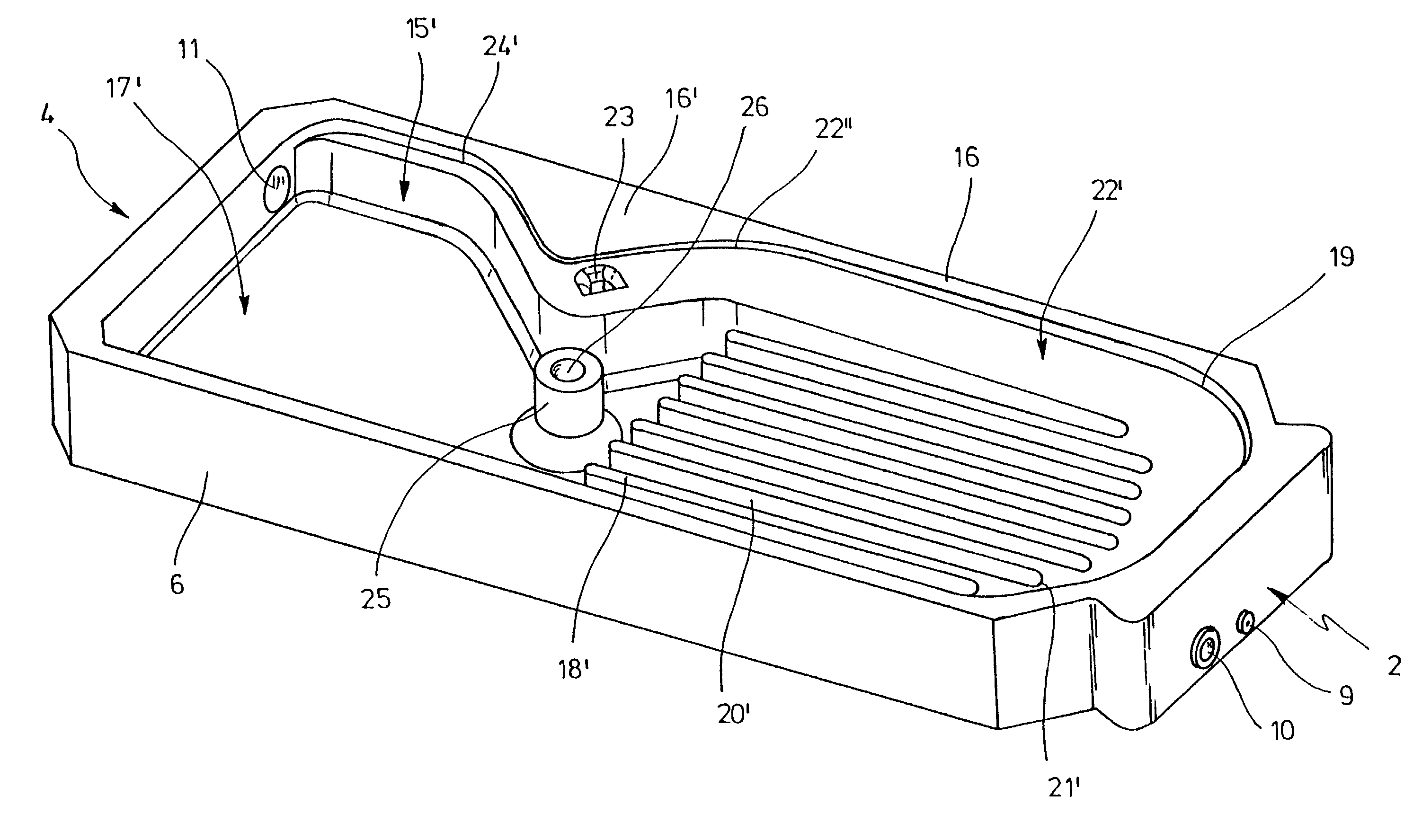
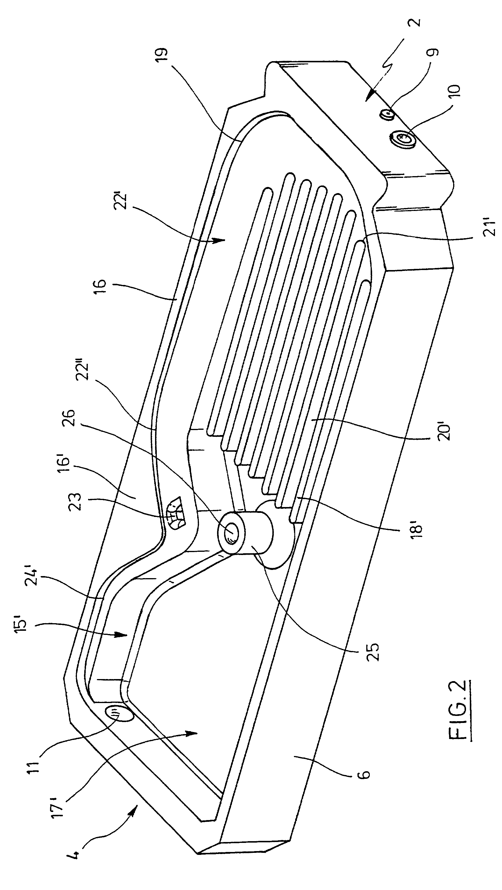
[0097]Furthermore, the body 1, more specifically the basic body 6, has a filling port 11, which is shown in FIG. 2, in the end face 2.

[0098]Adjacent to the catch contour 3″, the body 1 is connected, via a web 12, to an inscription flag 13 which is plate-shaped and is oriented perpendicularly to the body 1. A gap 14 is formed between the inscr...


PUM

PropertyMeasurementUnit
hydraulic diameteraaaaaaaaaa
volumesaaaaaaaaaa

Abstract

A microfluidic accumulating and proportioning component, including:a reservoir including an aeration port and an outlet disposed below for a liquid,capillary cavities in the reservoir,a displacement chamber which is disposed at least partly at the same level as the reservoir, with an inlet disposed above and a proportioning outlet disposed below for a liquid, anda rising capillary channel connecting the outlet of the reservoir to the inlet of the displacement chamber.

Description

BACKGROUND OF THE INVENTION[0001]1. Field of the Invention[0002]This invention relates to a microfluidic accumulating and proportioning component.[0003]2. Description of the Prior Art[0004]Microfluidic accumulating and proportioning components in the sense of this application serve for accumulating and / or and proportioning liquids. Such microfluidic components feature microstructures such as capillary channels or ports having characteristic dimensions which, for instance, include the hydraulic diameter of the channels in the range from 5 μm to 1,500 m (preferably from 10 μm to 500 μm) in one dimension. In particular, microfluidic proportioning components may have proportioning volumes in the nanoliter range and microliter range. They may be specifically manufactured from semiconductors and / or plastics and / or glass and / or ceramics and / or metals where appropriate manufacturing techniques of the micro-system technology or microstructuring may be employed, e.g. lithography and etching p...

Claims


Application Information

Patent Timeline
Patent Type & Authority Patents(United States)
IPC IPC(8): B01L3/02B01L3/00G01N35/10
CPCB01L3/0268B01L3/502723B01L2200/04B01L2200/0615B01L2200/0642G01N2035/1039B01L2200/16B01L2300/0816B01L2400/0406B01L2400/0487B01L2200/0684
Inventor HUHN, RUDIGERBLUM, ROGERSANDER, DIETMARTIMMANN, LUTZ
Owner EPPENDORF AG
Learn More