Eureka AIR delivers breakthrough ideas for toughest innovation challenges, trusted by R&D personnel around the world.

X-ray diffraction-based scanning system

Inactive Publication Date: 2006-06-20
VARIAN MEDICAL SYSTEMS
View PDF9 Cites 117 Cited by
  • Summary
  • Abstract
  • Description
  • Claims
  • Application Information

AI Technical Summary

Problems solved by technology

The demonstrated willingness of terrorists to die in the pursuit of their aims meant that 100% passenger-to-bag matching, which could be put in place rapidly, was not sufficient to counter an attempt to conceal explosives in checked baggage and bring down an airliner.
Successful screening for the presence of explosives presents numerous technological challenges, many of which are not met in present systems.
Thus, depending upon the level of the sensitivity setting, they either pass through a percentage of threat material, “missed detection” in security parlance, or they generate a high rate of false positives.
This parameter is not sufficiently specific to distinguish explosives from many other common materials.
This is time consuming and expensive for the airlines and the prospect of airport delays and the potential for theft is a source of concern to the traveling public.
Moreover, CT scanners are unable to detect the presence of explosive material that is formed into thin sheets because CT averages the x-ray absorption coefficient over each voxel.
Prior x-ray diffraction-based security systems for explosives detection and baggage scanning are not yet highly developed.
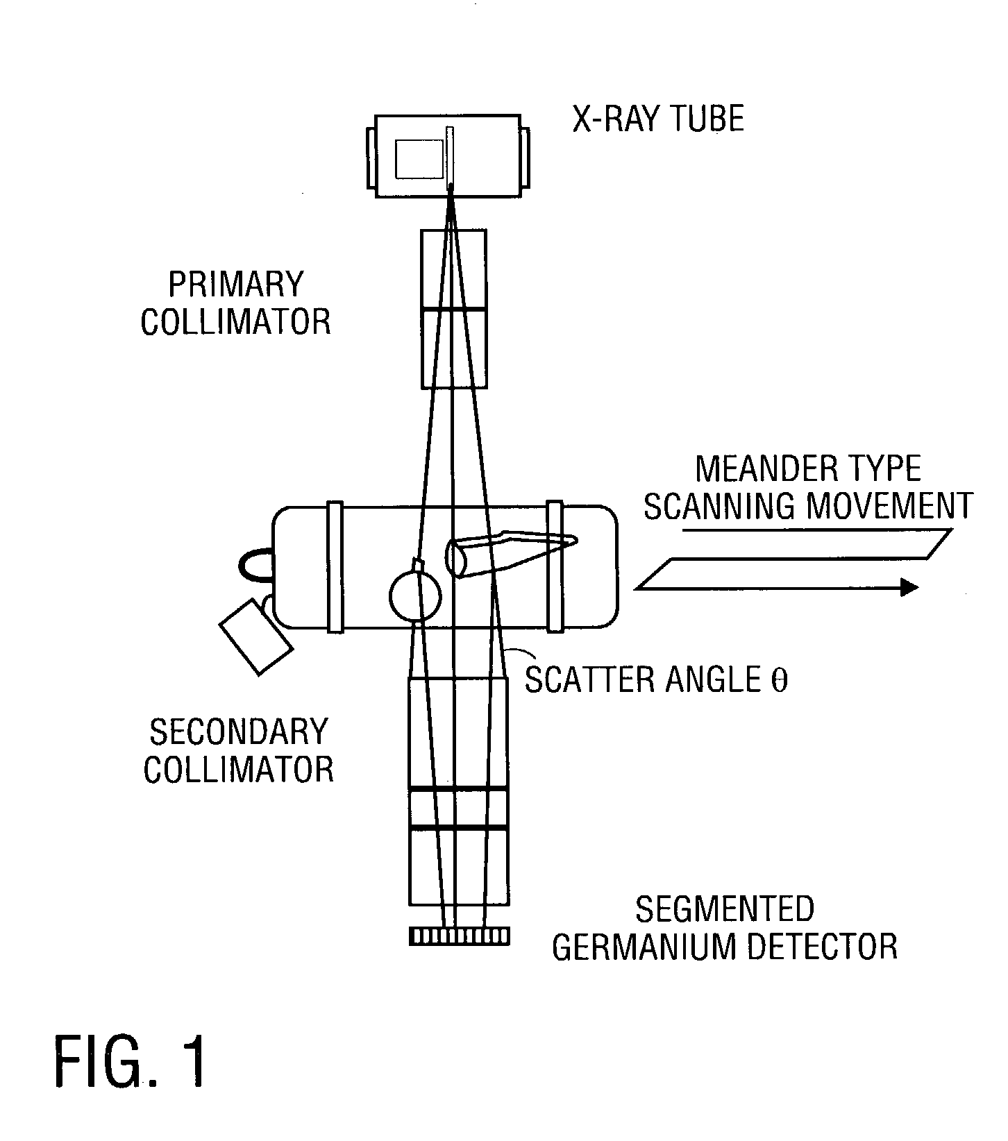
A divergent tight cluster of collimated x-ray pencil beams, originating from an effective point source, is directed through the bag under examination and sensed by the high-purity Ge detector cooled to liquid nitrogen temperature of −196 degrees C. However, such a system suffers from a number of fundamental constraints.
First, the high-purity Ge detector is too expensive to use in large area sensors.
Second, the requirement for liquid nitrogen cooling is cumbersome and expensive to maintain in an airport environment.
In addition, they can examine only a small area of a bag at one time due to the small detector size.
This is too slow for volume applications like routine baggage scanning.

Method used


Image

  • X-ray diffraction-based scanning system
  • X-ray diffraction-based scanning system
  • X-ray diffraction-based scanning system

Examples


Embodiment Construction

[0024]In the following description, numerous specific details are set forth such as examples of specific components, processes, etc. in order to provide a thorough understanding of the present invention. It will be apparent, however, to one skilled in the art that these specific details need not be employed to practice the present invention. In other instances, well known components or methods have not been described in detail in order to avoid unnecessarily obscuring the present invention.

[0025]The terms “above,”“below,” and “between” as used herein refer to a relative position of one layer or component with respect to another. As such, one layer deposited or disposed above or below another layer, or between layers, may be directly in contact with the other layer(s) or may have one or more intervening layers. Moreover, one component in front, behind, below or between another component may be in physical contact with the other component or may have one or more intervening components...


PUM


Abstract

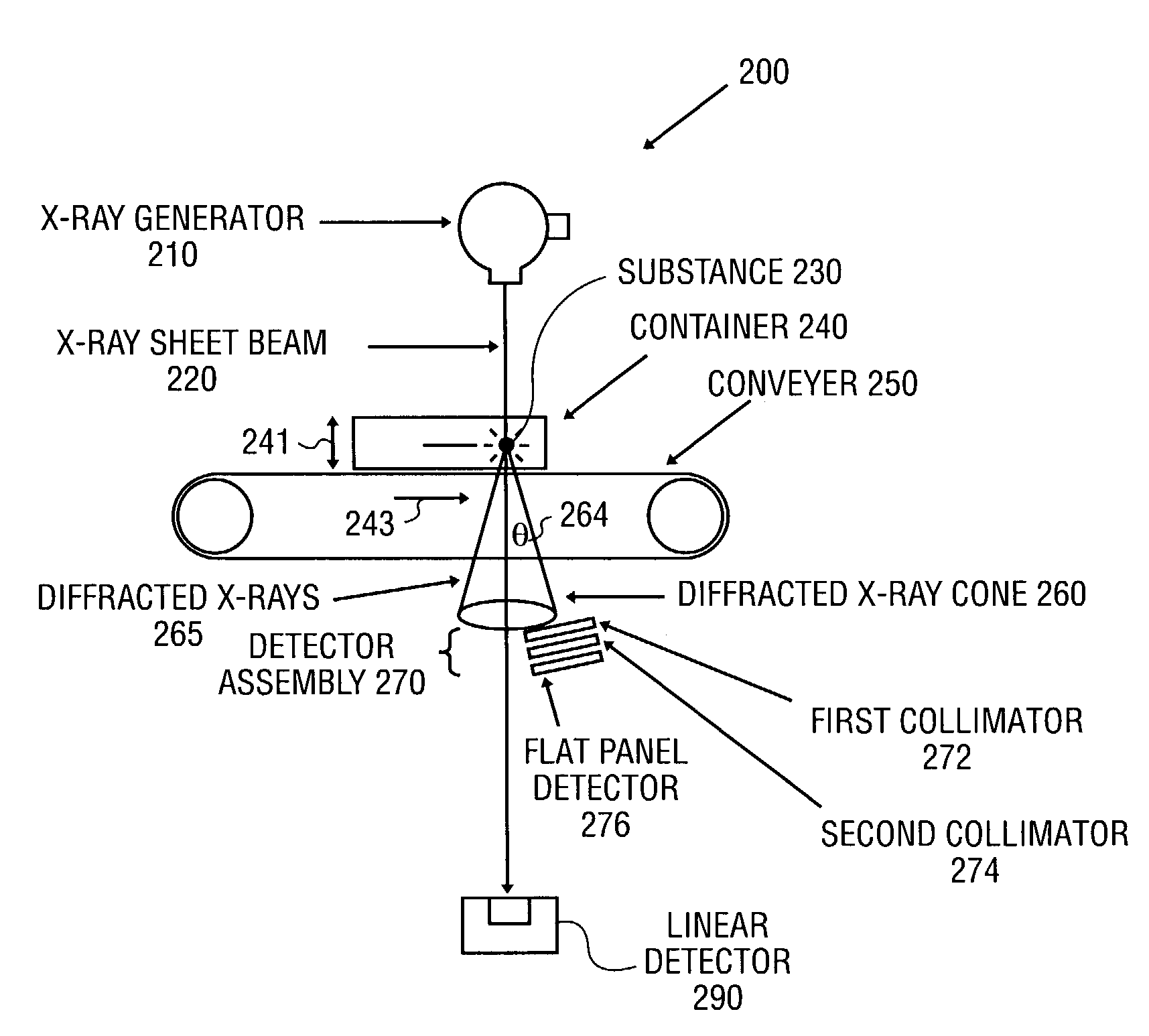
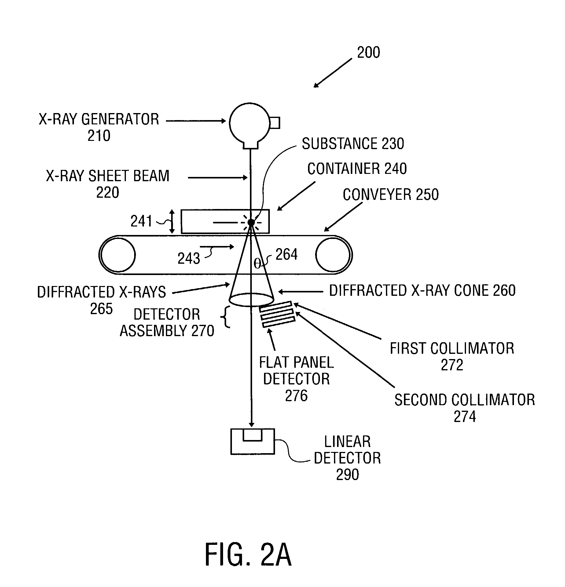
An x-ray diffraction-based scanning method and system are described. The method includes screening for a particular substance in a container at a transportation center using a flat panel detector having a photoconductor x-ray conversion layer to detect x-rays diffracted by a particular substance in the container. The diffracted x-rays may be characterized in different ways, for examples, by wavelength dispersive diffraction and energy dispersive diffraction.

Description

TECHNICAL FIELD[0001]This invention pertains to the field of x-ray scanning systems and, in particular, to x-ray diffraction-based scanning systems.BACKGROUND[0002]The events of Sep. 11th 2001 forced recognition of an urgent need for more effective and stringent screening of airport baggage. The need for security expanded from the inspection of carry-on bags for knives and guns to the complete inspection of checked bags for a range of hazards with particular emphasis upon concealed explosives. The demonstrated willingness of terrorists to die in the pursuit of their aims meant that 100% passenger-to-bag matching, which could be put in place rapidly, was not sufficient to counter an attempt to conceal explosives in checked baggage and bring down an airliner. Successful screening for the presence of explosives presents numerous technological challenges, many of which are not met in present systems. X-ray imaging is the most widespread technology currently employed for screening. Last ...

Claims


Application Information

Patent Timeline
IPC IPC(8): G01N23/04G01N23/20G21K5/10
CPCG01N23/20G01T1/2018G01V5/0025G01T1/247H01J35/06H01J35/26G01T1/244G21K5/10G01V5/222
Inventor GREEN, MICHAEL C.
Owner VARIAN MEDICAL SYSTEMS
Why Eureka
Eureka Blog
Learn More