
Rifle scope mounting means

a technology for rifle scopes and mounting means, which is applied to weapon components, sighting devices, weapons, etc., can solve the problems of not being provided with a suitable location, the receiver cover is not directly fixed, and the sks rifle has one major downside, so as to achieve a great platform for shooting and avoid losing any accuracy. , the effect of a rounded mounting platform

Inactive Publication Date: 2006-06-20
SCOUT IND INC
View PDF15 Cites 10 Cited by
  • Summary
  • Abstract
  • Description
  • Claims
  • Application Information

AI Technical Summary

Benefits of technology

"The present invention is a scope mounting means for the SKS rifle that replaces the original battle sight. The mount is securely attached to the rifle using the same structures that held the original sight in place, making it a very rugged platform for shooting optics. The mount allows for easy swapping of different scopes without losing accuracy. The invention also includes a central portion with at least one hole for receiving pins of the scope mount, and a right and left wing portion each with at least one hole for mounting additional scopes. The technical effects of the invention include improved accuracy and flexibility in shooting with different scope styles."

Problems solved by technology

However, the SKS rifle has one major downside; it is not provided with a suitable location for mounting a rifle scope.
The drawback of this approach is that the receiver cover is not directly fixed to the barrel itself, and as such accuracy is marginal at best.
In addition, the receiver cover has to be removed for cleaning, which causes additional loss of zero.
This setup also has problems, as the barrel heats up a shift in zero occurs owing to the expansion of the metal parts, and the unit must also be removed to clean the gas tube and port.

Method used


Image

  • Rifle scope mounting means
  • Rifle scope mounting means
  • Rifle scope mounting means

Examples


Embodiment Construction

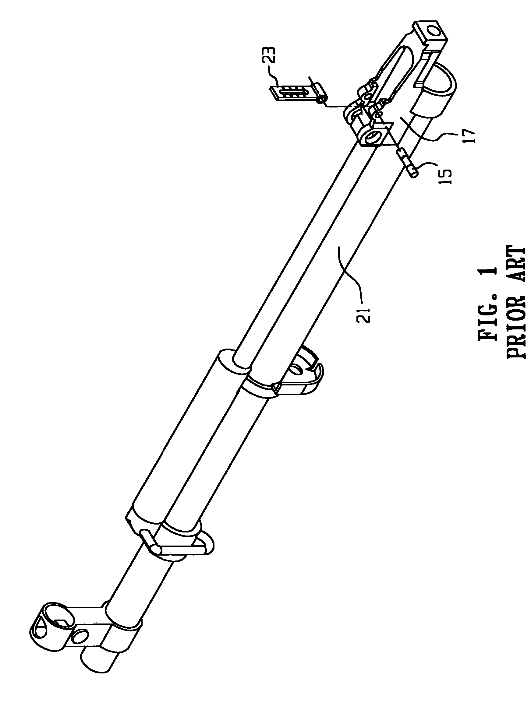
[0034]Referring to the drawings and initially to FIG. 1 there is shown an exploded perspective view of a rifle barrel according to the prior art and comprising what is commonly referred to in the art as a “battle sight”23, which battle sight is generally attached to a rear battle sight mount 17 by means of a roll pin 15, which is used to firmly secure the battle sight to the rifle. The battle sight 23 can be pivoted about the axis of the roll pin 15 from a horizontal, resting position to a vertical position. It is when the battle sight 23 is placed in its vertical position that it is ready for use, as is well-known in the art.

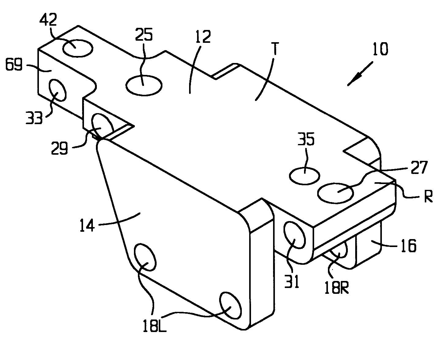
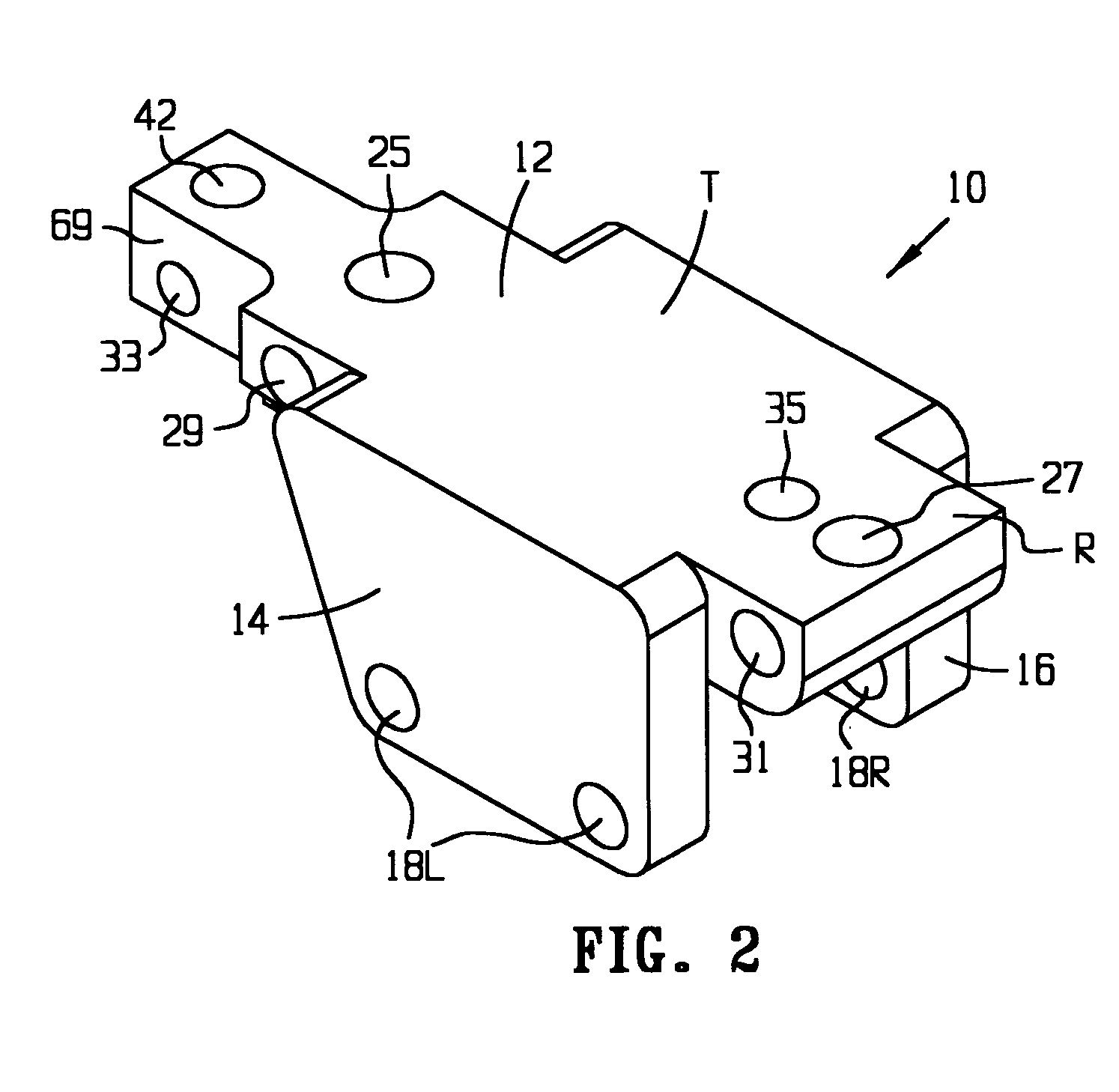
[0035]In FIG. 2 there is shown a perspective view of a sight base 10 according to the present invention. Such as sight base 10 comprises a central portion 12, which is provided with a left wing portion 14, and a right wing portion 16, wherein the left and right wing portions extend downwardly from the central portion 12, which central portion is substantially f...


PUM


Abstract

Provided herein is a sight base useful to render military-style rifles equipped with battle sights to be retrofitted with telescopic rifle scopes. Use of a device according to the invention provides sporting use and accuracy to rifles originally conceived as weapons of war, in a quick and convenient method. A sight base according to the invention is readily attached and detached from a rifle, and provides surprising accuracy owing to the rigid means by which a scope may be affixed to a rifle through use of the scope base provided herein.

Description

CROSS-REFERENCE TO RELATED APPLICATIONS[0001]This application claims the benefit of U.S. Provisional Application Ser. No. 60 / 492,658, filed Aug. 6, 2003, which application is incorporated herein by reference in its entirety.TECHNICAL FIELD[0002]This invention relates to a means for attaching a telescopic or other sighting means, such as red dot sights, to a rifle. More particularly, the present invention provides a device for retrofitting rifles originally equipped with open field sights, or “battle sights” with telescopic scope or other sighting device means known to those skilled in the art to enhance the aiming capabilities of a user of such firearm.BACKGROUND[0003]There are many firearms which are imported into the United States each year which are of foreign origin. Owing to low labor costs in countries foreign to the United States, the production costs for a given firearm may be significantly lower than similar arms produced within the United States. For the consumer, this tra...

Claims


Application Information

Patent Timeline
Patent Type & Authority Patents(United States)
IPC IPC(8): F41G1/387F41G11/00
CPCF41G11/001
Inventor WILSON, BRETT
Owner SCOUT IND INC
Learn More