Hand tool and knife for deburring

a deburring and hand tool technology, applied in drilling tools, turning tools, boring/drilling tools, etc., can solve the problems of difficult mechanism application, difficult blade manufacture, and difficult smooth rotation, and achieve the effect of facilitating smooth rotation

Inactive Publication Date: 2006-06-20
NOGA ENG & TECH 2008
View PDF30 Cites 6 Cited by
  • Summary
  • Abstract
  • Description
  • Claims
  • Application Information

AI Technical Summary

Benefits of technology

[0007]The present invention provides a hand tool that solves the above-mentioned problems, especially wear and tear of the shaft, thereby facilitating smooth rotation.

Problems solved by technology

A disadvantage of these known deburring tools is the fact that their blades are difficult to manufacture.
It would be difficult to apply a mechanism for blocking this rotation directly to the small round shaft of the blade, and such a mechanism would make a smooth rotation problematic.

Method used


Image

  • Hand tool and knife for deburring
  • Hand tool and knife for deburring
  • Hand tool and knife for deburring

Examples


Embodiment Construction

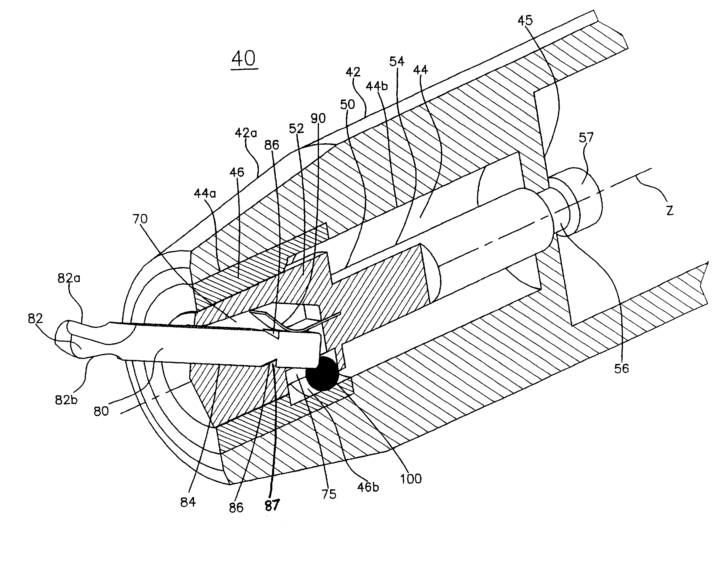
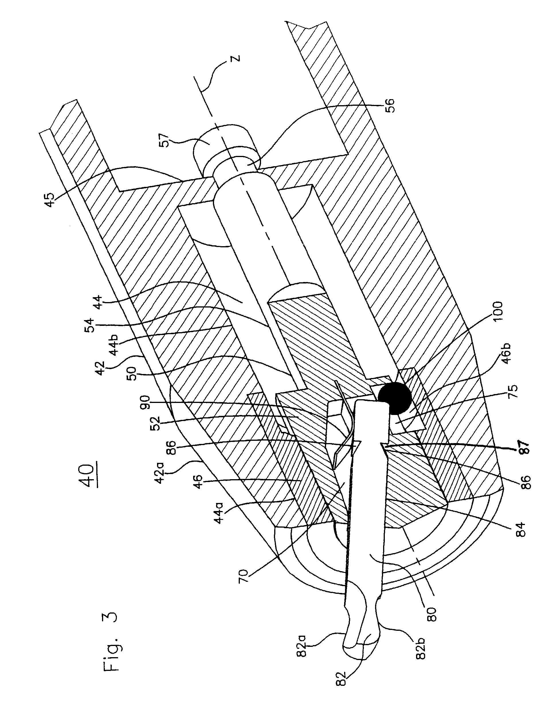
[0030]FIG. 3 shows, in a partially sectional view, the front part of a deburring tool 40 of the present invention. FIG. 3 shows housing 42 of deburring tool 40, said housing 42 may become part of the handle. This housing 42 has a circular section and tapers at its end 42a. Inside housing 42 is a bore, preferably a blind bore 44, which may reach into the handle of deburring tool 40. Longitudinally, bore 44 has a stepped section. As shown in FIG. 3, the front part 44a of bore 44, may be located at the front end 42a of housing 42, whereas a second part, 44b, of bore 44, may extend into the handle. The inside diameter of the front part of the bore, 44a, is larger than the inside diameter of the rear part 44b, of bore 44.

[0031]A cylindrical sleeve 46 is pressed into the front part 44a of bore 44. Sleeve 46 is shown in FIG. 6. This sleeve has at its front end a plain cylindrical bore 46a, and at its rear end a larger bore 46b. In the area of the step thus formed, are many recesses 48, eac...


PUM

PropertyMeasurementUnit
axis of rotationaaaaaaaaaa
rotationaaaaaaaaaa
axial movementaaaaaaaaaa

Abstract

A hand tool for deburring is provided, as well as a cutting blade to be inserted into the tool, the tool comprising a housing, and a rotatable holding device, the holding device being positioned in and being rotatable in the housing and having a chamber for releasably holding a cutting blade, the chamber running obliquely to the axis of rotation (z) of the holding device.

Description

TECHNICAL FIELD OF THE INVENTION[0001]This invention relates to a manual deburring tool, and a blade which can be inserted into it.BACKGROUND OF THE INVENTION[0002]Hand tools for deburring sharp corners, using rotating blades, are known in the art. Such hand tools consist of a handle and a cutting blade, which is made of round wire that has been bent into the form of a crank. The blade rotates in a longitudinal hole of the handle, and the cutting edge of said blade follows along the edge of a hole or straight line of a part to be deburred. Such hand tools are used mostly in the metalworking and plastics industries.[0003]FIG. 1 shows a known deburring tool 10. It consists of a handle 12 and a housing 14. Housing 14 may be made in a single piece with handle 12. Alternatively, handle 12 could be made as a separate part, which can be fastened removably to the housing. A blind hole 16 is drilled into the housing 14, into which the round shaft 18 of a cutting blade 20 is inserted. This ro...

Claims


Application Information

Patent Timeline
Patent Type & Authority Patents(United States)
IPC IPC(8): B26B3/00B26B1/00B23B51/10B26B5/00
CPCB23B51/101B26B5/00Y10T408/95Y10T408/553
Inventor HIRSCH, SHALOM
Owner NOGA ENG & TECH 2008
Why Eureka
Try Eureka