
Pipeline controller for providing independent execution between the preliminary and advanced stages of a synchronous pipeline

Inactive Publication Date: 2006-06-06
UNISYS CORP
View PDF8 Cites 8 Cited by
  • Summary
  • Abstract
  • Description
  • Claims
  • Application Information

AI Technical Summary

Benefits of technology

[0017]It is another object to provide a synchronous pipeline design capable of causing instructions to advance within a first portion of the pipeline in a manner that is independent from the manner in which instructions advance through the second portion of the pipeline;
[0020]It is yet another object to provide a pipeline design that allows processing to stall waiting for a predetermined condition to occur within a first portion of the pipeline while additional instructions continue to enter a second portion of the pipeline.
[0023]In general, instructions and the associated decoded instruction signals are passed from one logic section to the next within the pipeline at predetermined increments of time, which in the preferred embodiment is one period of the system clock. Typically, each logic section retains an instruction for processing for one clock cycle, then provides any processing results to a different logic section associated with a subsequent pipeline stage for continued processing. The timing requirements of each logic section are tuned to be similar to the requirements of the other logic sections within the pipeline for the majority of instructions in the instruction set so that instructions can be passed from one logic section to the next with optimal efficiency.
[0028]From the foregoing description, the reader will appreciate that instructions continue to advance within all fetch stages of the pipeline until each of those fetch stages, including the pre-decode and decode logic stages, contains a respective instruction. Moreover, instruction retrieval will continue until the queue is full. Only then will instructions cease to enter the fetch stages of the pipeline until instruction execution resumes in a standard (non-extended) manner within the execution stages of the pipeline. The pre-decode and decode logic sections can complete pre-decode and decode operations, respectively, for the instructions resident in those stages during the extended-mode execution cycles. This maximizes system throughput by ensuring that completely overlapped pipeline execution will occur following the completion of the extended-mode execution cycles.

Problems solved by technology

This may diminish processor throughput, particularly in those systems having a complex and diverse instruction set architecture.
This type of pipeline is relatively simple to design, but is generally logic intensive.
Moreover, the time required to store and retrieve processing results from the FIFO can slow pipeline execution.
Although fewer storage locations are needed to implement this design, the control logic is more complex.
Additionally, the time required to execute the handshaking mechanism slows throughput.
The resulting system is relatively logic intensive.
However, because each of the synchronized stages operates in a lock-step fashion, inefficiency still exists in those situations in which the pipeline is partially emptied.
This may occur, for example, when a cache miss situation occurs.
As a result, the instruction can not be provided to the pipeline in the time required to keep the pipeline filled.
As a result, several clock cycles are wasted to fill the pipeline.
A scenario similar to that described above results when a cache miss occurs during an operand fetch associated with one of the instructions executing in the pipeline.
Thus, fully overlapped execution can not be resumed until some time after the instruction associated with the operand cache miss has completed execution.
This decreases system throughput.
The above examples illustrate that manner in which lock-step synchronous pipeline operation may, in some instances, create inefficiency.
However, this occasional inefficiency has been considered an acceptable trade-off to the costly overhead and undue complexity associated with asynchronous designs.

Method used


Image

  • Pipeline controller for providing independent execution between the preliminary and advanced stages of a synchronous pipeline
  • Pipeline controller for providing independent execution between the preliminary and advanced stages of a synchronous pipeline
  • Pipeline controller for providing independent execution between the preliminary and advanced stages of a synchronous pipeline

Examples


Embodiment Construction

The Instruction Processor Environment of the Current Invention

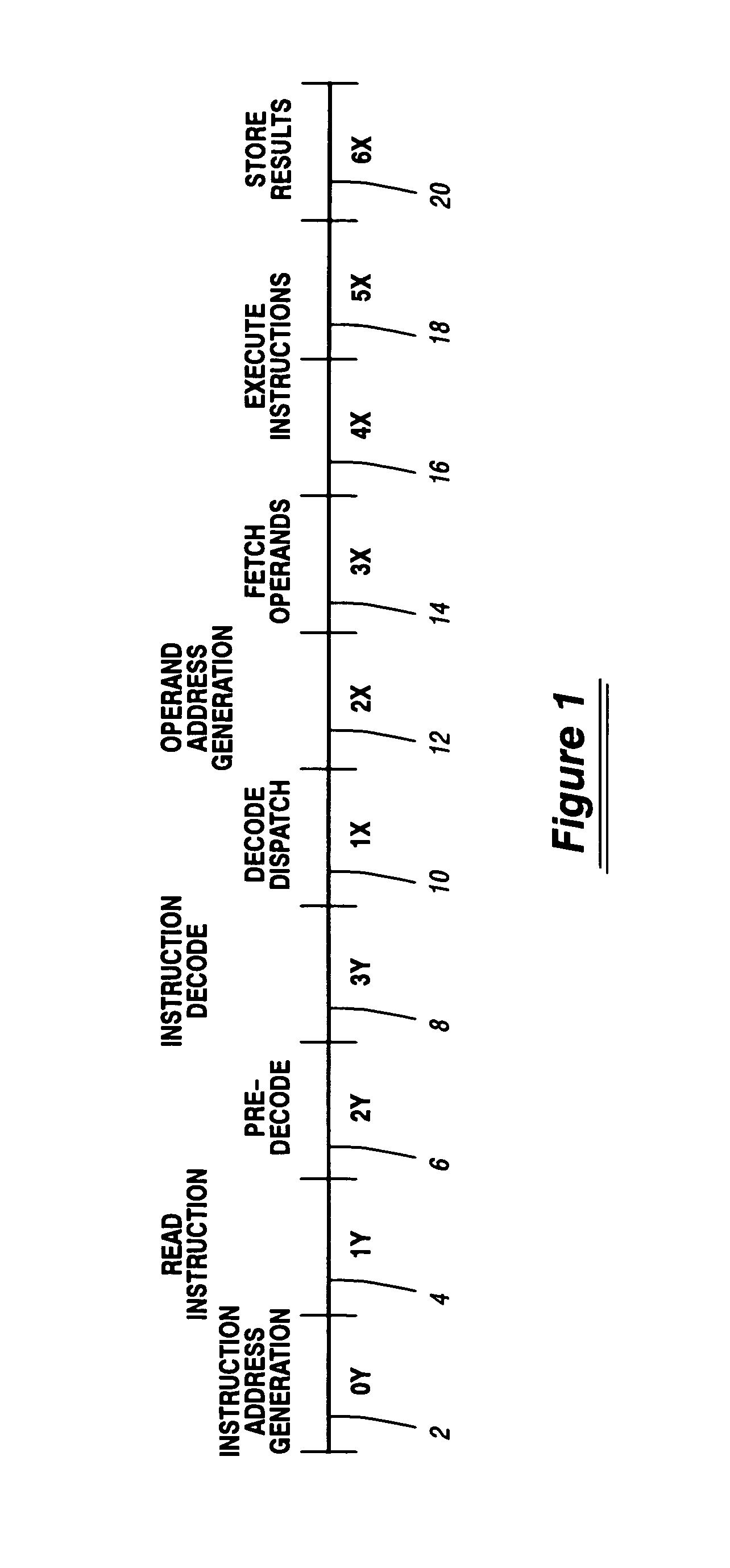
[0047]FIG. 1 is a timing diagram showing pipelined execution of an instruction by an exemplary Instruction Processor (IP). Pipelined instruction execution is a method of increasing system throughput by dividing the execution of each instruction into functional operations that can be performed within different logic sections of the IP. Since each logic section of the IP can be processing somewhat independently from the other logic sections, the IP can be executing portions of several instructions at one time so that instruction execution is overlapped.

[0048]The timing diagram of FIG. 1 shows a standard instruction being divided into ten functional operations. Each of these functional operations may be referred to as stage of execution.

[0049]During the first stage, designated as the “0Y” stage 2, address generation occurs for the instruction. Next, the instruction is retrieved from cache memory during the “1Y” stage 4. Foll...


PUM


Abstract

A synchronous pipeline design is provided that includes a first predetermined number of fetch logic sections, or “stages”, and a second predetermined number of execution stages. Instructions are retrieved from memory and undergo instruction pre-decode and decode operations during the fetch stages of the pipeline. Thereafter, decoded instruction signals are passed to the execution stages of the pipeline, where the signals are dispatched to other execution logic sections to control operand address generation, operand retrieval, any arithmetic processing, and the storing of any generated results. Instructions advance within the various pipeline fetch stages in a manner that may be independent from the way instructions advance within the execution stages. Thus, in certain instances, instruction execution may stall such that the execution stages of the pipeline are not receiving additional instructions to process. This may occur, for example, because an operand required for instruction execution is unavailable. It may also occur for certain instructions that require additional processing cycles. Even though instructions are not entering the execution stages, instructions may continue to enter the fetch stages of the pipeline until all fetch stages are processing a respective instruction. As a result, when normal instruction execution resumes within the execution stages of the pipeline, all fetch stages of the pipeline have been filled, and pre-decode and decode operations have been completed for those instructions awaiting the entry into the execution stages of the pipeline.

Description

FIELD OF THE INVENTION[0001]This invention relates to a system and method for controlling the flow of instructions through a synchronous instruction pipeline within an instruction processor; and, more particularly, to a system that allows instruction processing to continue within first predetermined stages of the synchronous instruction pipeline independently of instruction execution occurring within second predetermined stages of the pipeline.DESCRIPTION OF THE PRIOR ART[0002]Many of today's high-speed digital instruction processors utilize a pipelined architecture. In pipelined architectures, several instructions are being executed within the Instruction Processor (IP) logic at the same time. An instruction is partially executed by a first section of the IP logic, is then passed to another section of the IP logic to undergo a second phase of processing, and so on. In an exemplary IP pipeline, a first section of the IP may be executing the hardware sequences associated with an inst...

Claims


Application Information

Patent Timeline
IPC IPC(8): G06F9/40
CPCG06F9/3869G06F9/3867
Inventor HARTNETT, THOMAS D.KUSLAK, JOHN S.LUCAS, GARY J.
Owner UNISYS CORP
Learn More