
Roof box device and roof module with integrated roof box device

a roof module and roof box technology, applied in the direction of roofs, superstructure subunits, supplementary fittings, etc., can solve the problems of conventional roof box devices, and achieve the effect of cost-effective, flexible and fast production

Inactive Publication Date: 2006-06-06
DECOMA GERMANY
View PDF13 Cites 13 Cited by
  • Summary
  • Abstract
  • Description
  • Claims
  • Application Information

AI Technical Summary

Benefits of technology

[0005]The roof module in accordance with the invention is designed for a motor vehicle and is manufactured preferably from a plastic wherein a roof box device is integrally formed with the roof module in one piece. Thus, the roof box device is integrated as part of the roof module and is a direct component of the roof module. Manufacture of the roof module from a plastic permits a great extent of freedom in the design or concrete configuration of the roof box device and, furthermore, offers the advantage of cost-effective, flexible and speedy production. In all cases the roof box device has an upper shell though the roof box device may optionally have a bottom shell as well.
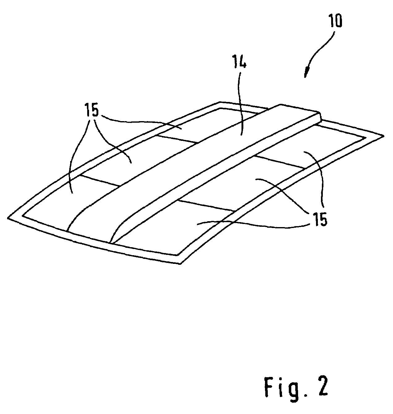
[0006]In an advantageous embodiment, the roof box device may completely cover a length of the roof module although it may be formed to be located substantially centrally in the roof module over part of the width. Transparent structural elements may be set into the roof module contiguous with the roof box device arranged in the middle, for example to allow better incidence of daylight into the interior of the vehicle. Such transparent structural elements, subsequently referred to only as glass elements, are made favorably from a conventional laminated safety glass or a polycarbonate plastic, preferably with a scratch-proof hard coating which leads to further weight advantages for the roof module.
[0007]There are any number of possible variations with regard to the width and length of the roof box device as a component part of the roof module depending in each case on the stowage volume required for the roof box device and the manufacturer's design specifications. For example, it is possible to develop the roof box device so that in length it only extends over a rear part of the roof module, that is above the area of the back seats, while a transparent structural element is set into the front area of the roof module above the driver and passenger seats. As already explained, the plastic material used opens up a great extent of design freedom when configuring the roof module with the integrated roof box device.
[0009]The roof box device has an exceptionally high level of functionality in that it is accessible either from the outside of the vehicle and / or also from the interior of the vehicle by way of appropriate flap devices or the like, and in that it is no problem to gain access to the inside of the roof box device from the interior of the vehicle. In this case at least one hinged flap or at least one sliding element or the like is fitted to the roof box device so that the bottom shell and thus the roof box device can be opened in the direction of the vehicle's interior. The variability of the roof box device may be favorably increased in that, furthermore, at least one supporting element is provided between the top shell and the bottom shell in the form of an intermediate cover that is guided along the longitudinal sides of the roof box device. If the intermediate shelf extends along the entire length of the roof box device, it is possible for example, to store elongated and heavy objects underneath the intermediate shelf while smaller and lighter objects are placed on the intermediate shelf. This also applies vice versa wherein heavy objects may also be placed on the intermediate shelf and smaller and lighter objects may be placed under the intermediate shelf, i.e. above an upper side of the bottom shell.
[0020]When using the roof module in accordance with the invention for a motor vehicle, it is very advantageous from a production engineering point of view if the attachment point of the vehicle's roof area, which connection point is defined by a margin running around the roof rails, can always be selected to be the same. Accordingly, regardless of the embodiment of the roof module, there are no alterations necessary when getting the vehicle's sheet-metal body ready in which retaining areas are provided for fitting in the roof module, which has an extremely favorable effect on cost-effective production of the entire vehicle. Furthermore, with the roof module in accordance with the invention, it is possible to attach the roof module to the body using a so-called zero-tolerance joint so that the roof module finishes flush with the body or with the roof rails adjacent to it.

Problems solved by technology

As a result, conventional roof box devices are subject to the disadvantage that they can only be used either in conjunction with roof rack systems or that they must have complicated fixing devices to ensure reliable attachment while the vehicle is being driven during which time considerable forces, particularly in the form of wind load, act on the roof box device.
Furthermore, conventional roof box devices that are attached to a vehicle roof only allow access from outside whereby the lid of the roof box device is swung open or suchlike.

Method used


Image

  • Roof box device and roof module with integrated roof box device
  • Roof box device and roof module with integrated roof box device
  • Roof box device and roof module with integrated roof box device

Examples


Embodiment Construction

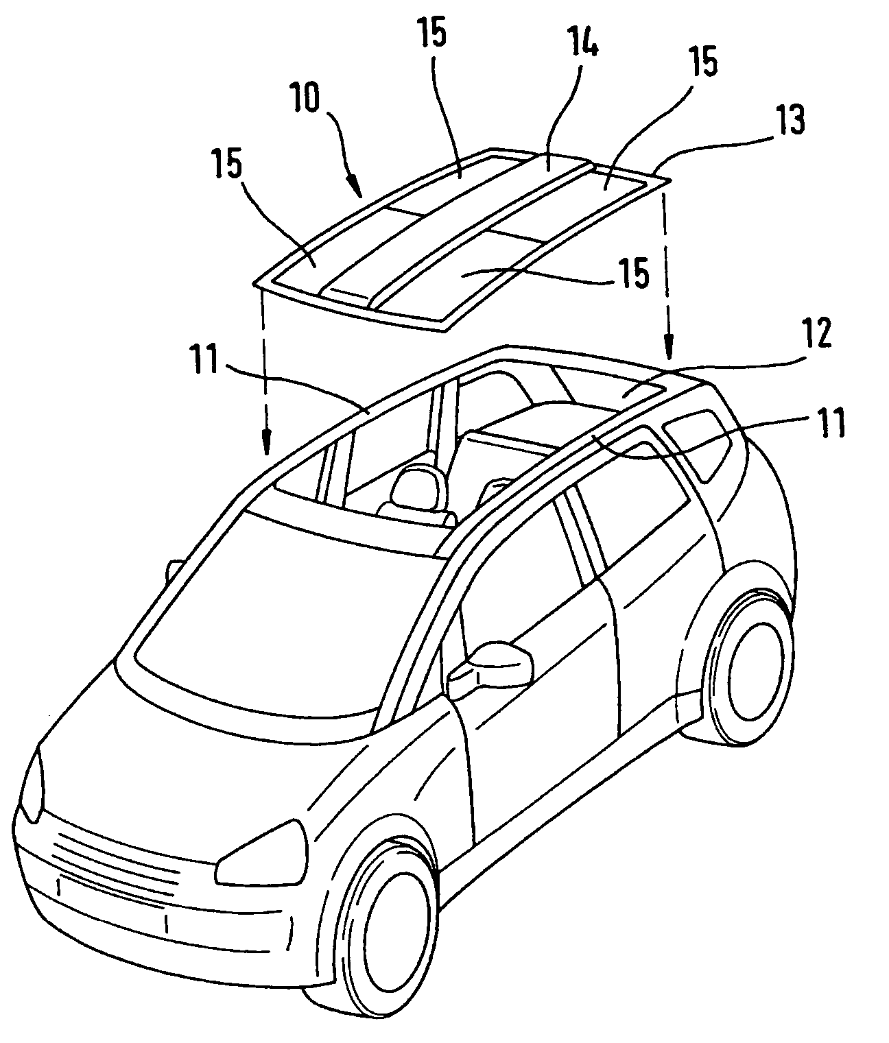
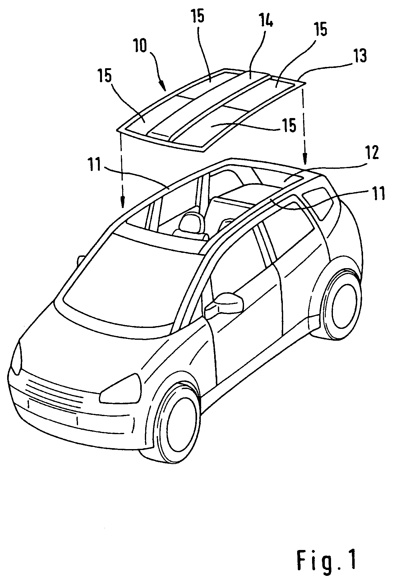
[0030]FIG. 1 shows an embodiment of the roof module 10 in accordance with the invention for assembly with a roof area of a motor vehicle. The vehicle's roof area includes roof rails 11 between which a corresponding opening 12 is formed, which is adapted to the dimensions of the roof module 10. If the roof module 10 is suitably connected to the roof rails 11, e.g. by bonding or the like, the roof module 10 completely covers the opening 12.

[0031]The roof module 10 has a frame 13 running around it that is preferably suitably bonded to roof rails 11. A roof box device 14 that covers the entire length of the roof module 10 is formed in the direction longitudinal to the roof module 10. In this case the roof box device 14 is designed to be integrated in the roof module 10 in one piece. If the roof box device 14 has a top shell 20 and a bottom shell 21 (see FIG. 5), the top shell 20 is preferably formed as a part of the outer surface of the roof module 10.

[0032]Adjacent to the roof box devi...


PUM


Abstract

A roof module of a motor vehicle, wherein the roof module is manufactured from a plastic and a roof box device is integrally formed with the roof module in one piece.

Description

FIELD OF THE INVENTION[0001]The invention relates to a roof module and roof box device for a roof module of a motor vehicle.BACKGROUND OF THE INVENTION[0002]So-called roof box devices that are fitted as an accessory to the roof of a motor vehicle and that considerably increase the available stowage volume in addition to the vehicle's normal luggage compartment have been known for a long time. As a rule, conventional roof box devices are attached to roof rack systems or are connected directly with the vehicle roof by means of attachment feet, claws or the like. As a result, conventional roof box devices are subject to the disadvantage that they can only be used either in conjunction with roof rack systems or that they must have complicated fixing devices to ensure reliable attachment while the vehicle is being driven during which time considerable forces, particularly in the form of wind load, act on the roof box device.[0003]Furthermore, conventional roof box devices that are attach...

Claims


Application Information

Patent Timeline
Patent Type & Authority Patents(United States)
IPC IPC(8): B60J7/00B60R9/055B62D25/06B62D29/04B62D65/04
CPCB60R9/04B60R9/055B62D65/04B62D29/043B62D25/06
Inventor OZKOK, KERIMKONIG, MICHAELLUDWIG, HANS-JOACHIM
Owner DECOMA GERMANY
Learn More