
Variable-gain low noise amplifier to reduce linearity requirements on a radio receiver

Active Publication Date: 2006-05-30
NXP BV
View PDF19 Cites 34 Cited by
  • Summary
  • Abstract
  • Description
  • Claims
  • Application Information

AI Technical Summary

Benefits of technology

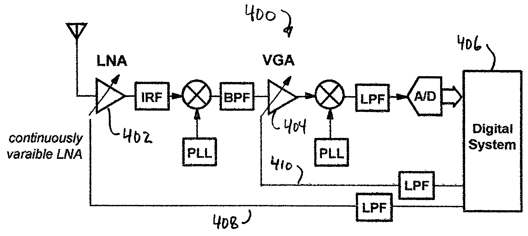
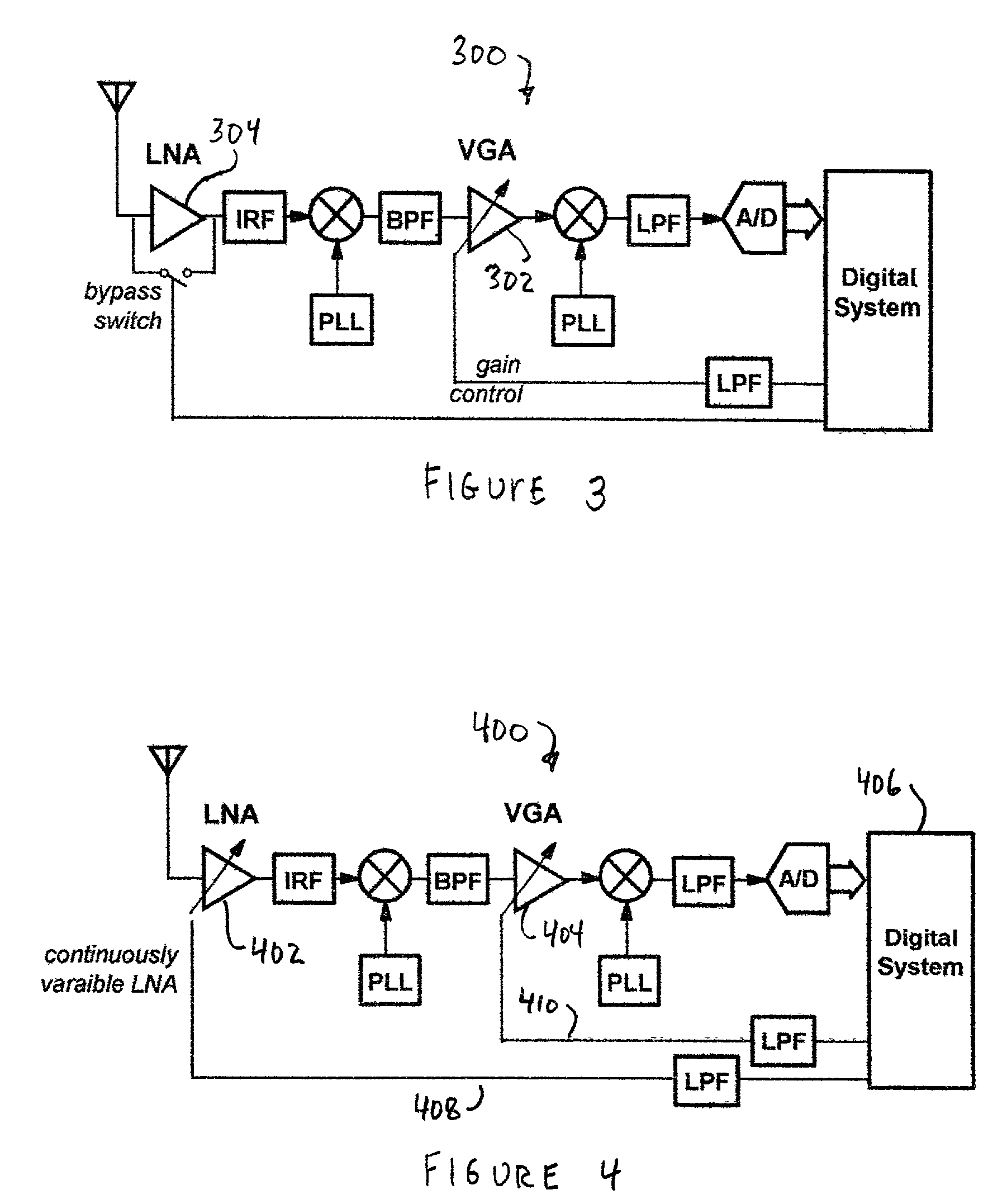
[0015]In another embodiment included in the present invention, a method is provided for operating a receiver to receive an RF signal for demodulation. The receiver comprises an LNA with continuously variable gain that receives the RF signal and produces an LNA output signal coupled to a VGA. The LNA and VGA have control inputs to receive control signals that set gain factors of the LNA and VGA, respectively. The method comprises the steps of determining that a received power level of the RF signal is varying within a first selected power range, maintaining the gain factor of the VGA, and adjusting the gain factor of the LNA so that a signal-to-noise ratio required for demodulation of the RF signal is met with a selected margin and the linearity requirements of the receiver are reduced.

Problems solved by technology

A critical building block in a radio receiver is the low noise amplifier (LNA).
As such, the performance of the LNA greatly affects the sensitivity of the radio receiver.
As a result, the first stage or first few stages set the noise factor of the radio receiver system.
Interfering signals can interact and produce intermodulation distortion products that degrade the quality (signal-to-distortion ratio) of the signal.
The intermodulation distortion power increases rapidly with the interfering signal power.
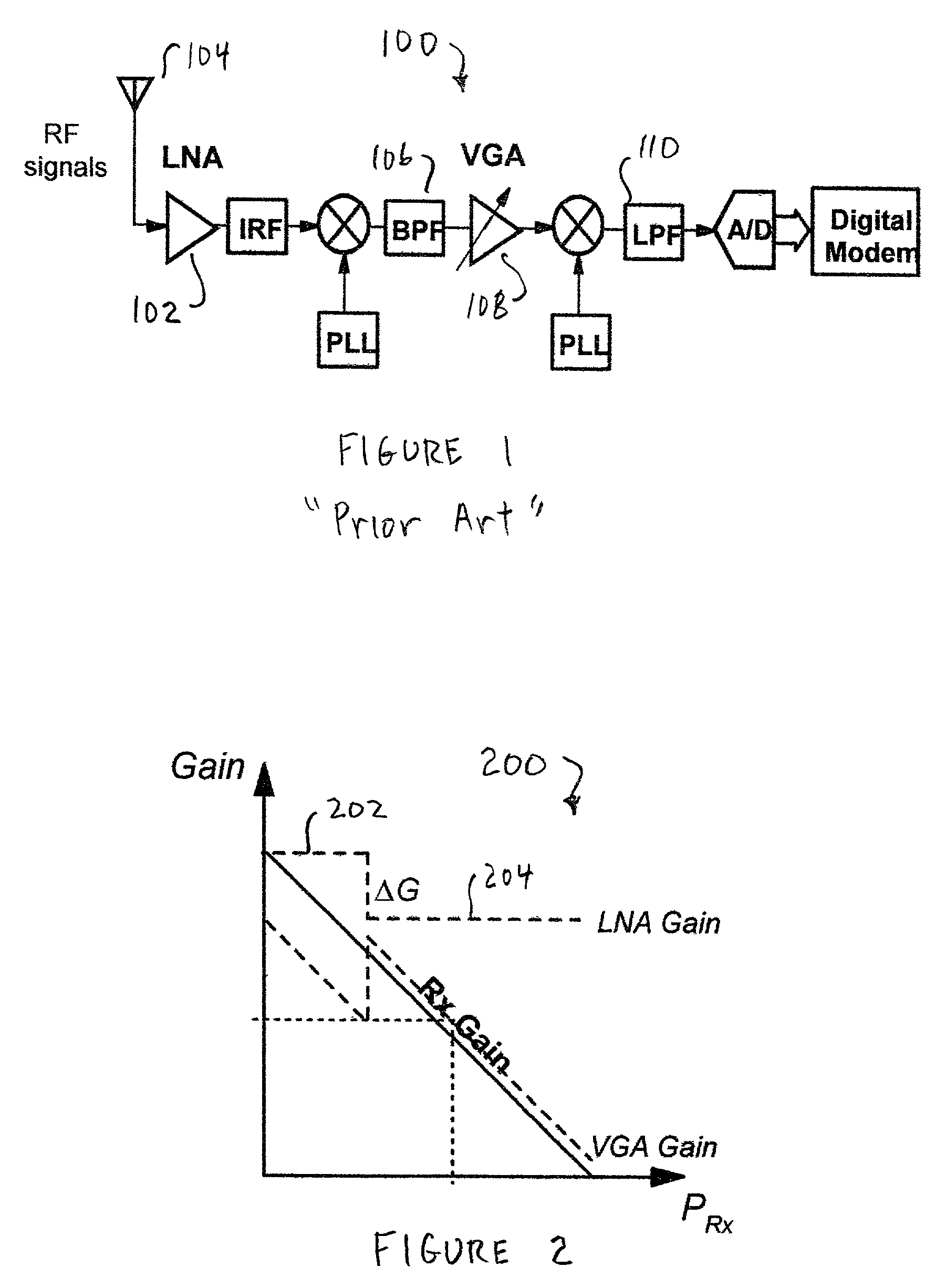
Unfortunately, the switching approach described above places great stress on the linearity of the radio system just prior to switching the gain of the LNA, and amplifies the received signal power high above the receiver's noise floor—much more than required.

Method used


Image

  • Variable-gain low noise amplifier to reduce linearity requirements on a radio receiver
  • Variable-gain low noise amplifier to reduce linearity requirements on a radio receiver
  • Variable-gain low noise amplifier to reduce linearity requirements on a radio receiver

Examples


Embodiment Construction

[0025]The present invention includes a system having an LNA with continuously variable gain. The gain of the LNA is varied with the power level of the desired received signal such that the signal to noise ratio required for demodulation is met with some margin and the linearity requirements of the radio receiver are eased. Thus, various embodiments of the present invention are described in detail in the following text.

[0026]The power level of the desired received signal input to the LNA can be measured in a variety of ways. In most radio receivers, a received signal strength indicator (RSSI) signal is available. It measures the total signal power after filtering and includes amplified noise, attenuated interfering signals, and intermodulation distortion products. Another method to determine the received signal power is by estimates of the bit energy per spectral noise density (Eb / No). This is practical in digital communication systems and is a better indication of the signal's power...


PUM


Abstract

Variable gain low noise amplifier (LNA) system to reduce linearity requirements on a radio receiver. In the receiver, the LNA is coupled to receive an RF signal and produce an amplified signal at an LNA output. The receiver also comprises a VGA coupled to the LNA output to receive the amplified signal and produce a VGA output to downstream components of the receiver. The receiver also comprises a control network coupled to the LNA and the VGA. The control network operates to adjust gain factors of the continuously variable LNA and the VGA based on a received power indicator of the RF signal, so that a signal-to-noise ratio required for demodulation of the RF signal is met with a selected margin and the linearity requirements of the receiver are reduced.

Description

CROSS REFERENCE TO RELATED APPLICATIONS[0001]This application claims the benefit of priority from a co-pending U.S. Provisional Application entitled, “VARIABLE Gain LOW NOISE AMPLIFIER to REDUCE LINEARITY REQUIREMENTS ON A RADIO RECEIVER” filed on Jan. 16, 2001, and having application No. 60 / 261,962.FIELD OF THE INVENTION[0002]This invention relates generally to radio receiver circuitry, and more particularly, to radio receiver system including a variable-gain low noise amplifier controlled in a manner to reduce the linearity requirements of the system.BACKGROUND OF THE INVENTION[0003]A critical building block in a radio receiver is the low noise amplifier (LNA). The LNA amplifies the received signal and boosts its power above the noise level produced by subsequent circuits. As such, the performance of the LNA greatly affects the sensitivity of the radio receiver.[0004]FIG. 1 shows a diagram of a typical radio receiver 100. The radio receiver 100 includes a LNA 102 that receives rad...

Claims


Application Information

Patent Timeline
IPC IPC(8): H04B1/06
CPCH04B1/28H03G3/3068
Inventor GROE, JOHN B.
Owner NXP BV
Learn More