
Wireless network system and method for providing same

a wireless network and wireless technology, applied in the field of digital computer networks, can solve the problems of ricochet network creating a great deal of “packet duplication”, limited use, and inability to connect to the network, so as to achieve the effect of updating and improving the link, and being robust and efficien

Inactive Publication Date: 2006-05-30
IPCO
View PDF10 Cites 248 Cited by
  • Summary
  • Abstract
  • Description
  • Claims
  • Application Information

AI Technical Summary

Benefits of technology

The system achieves robust and efficient wireless communication by allowing multiple link choices, optimizing data paths, and ensuring network stability even under adverse conditions, such as client loss or mobility, by dynamically updating communication links.

Problems solved by technology

While the use of the Internet has been prevalent for many years now, its use has been limited by the arcane and often difficult commands required to access the various resources of the network.
For one, if the radio modem of the personal computer is not within transmission range of one of the transceivers of the Ricochet network, a connection cannot be made to the network.
Furthermore, the Ricochet network can create a great deal of “packet duplication” or “pollution” as copies of a particular data packet are multiply repeated, rather than routed.
While duplicate packets are ultimately discarded, such duplicate packets increase data congestion in the network and increases the work that must be performed by the server.
In addition, since data packets are transmitted from all the transceivers of the Ricochet network, there may be packet duplication at the personal computer if it is in contact with more than one transceiver of the Ricochet network, and the bandwidth available from each transceiver is reduced since each transceiver is transceiving each client-destined data packet on the network.
Also, since the data is transmitted to the Internet over twisted pair, there is a 28.8K baud bottleneck in the system, resulting is average system performance of even less than 28.8K baud.
It is therefore apparent that prior art wireless networks of the Ricochet network type lack robustness (i.e. the ability to maintain communication with the network under adverse conditions) and exhibit a number of inefficiencies such as data packet proliferation.
Cellular telephone systems operate using a number of transceivers, where each transceiver occupies a “cell.” As a mobile telephone moves from one cell to another, an elaborate and expensive land-based system causes the mobile telephone to be “handed-off” from the cell that it was previously in to the cell that it is entering.
As noted, the equipment and system used for the hand-off is expensive and, further, such hand-off sometimes fail, dropping the telephone connection.
Furthermore, individual radios at a given cell can handle only one call at a time, which is inadequate for many computer network systems.
With this protocol, each peer repeats all data packets that it receives, resulting in rapid packet proliferation.
In fact, with this protocol, so many packet collisions occur among the peers that the packets may never reach the intended peer.
Lastly, there is abundant reporting in the literature, but it cannot be substantiated, that the U.S. Military has a wireless communication system which allows digital information to be transmitted in a more robust and efficient matter.
However, source code listings, or source code in machine-readable form for these U.S. military systems remains secret and unavailable to the public.
The prior art does not disclose, however, a packet-based wireless computer network that is both robust and efficient, wherein each client of the network can be efficiently and effectively in communication with a multiplicity of other clients and servers of the network, greatly multiplying the number of link choices available and, if conditions change, or if a better link to a server becomes known to a client, where the link for a client can be updated and improved.

Method used


Image

  • Wireless network system and method for providing same
  • Wireless network system and method for providing same
  • Wireless network system and method for providing same

Examples


Embodiment Construction

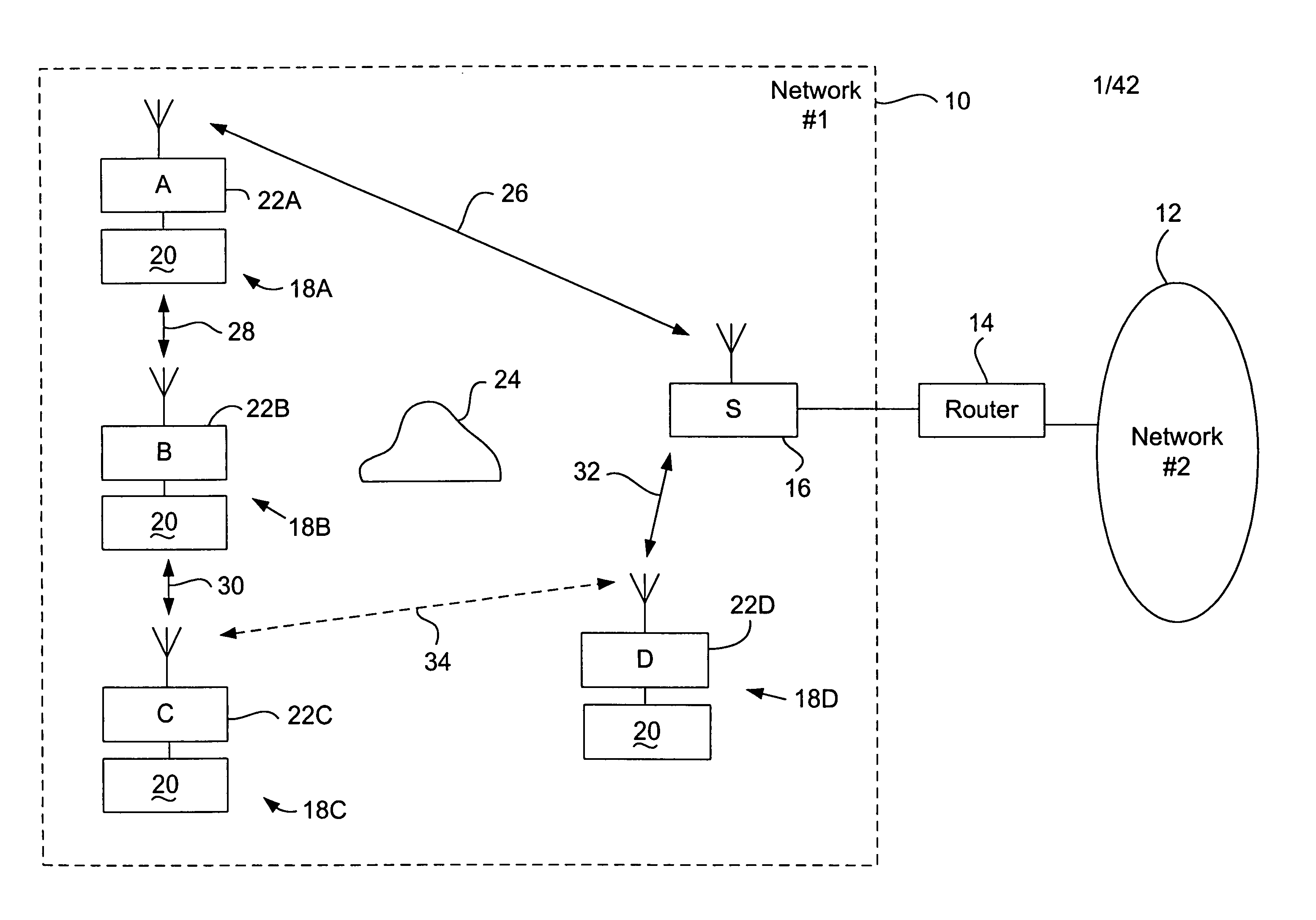
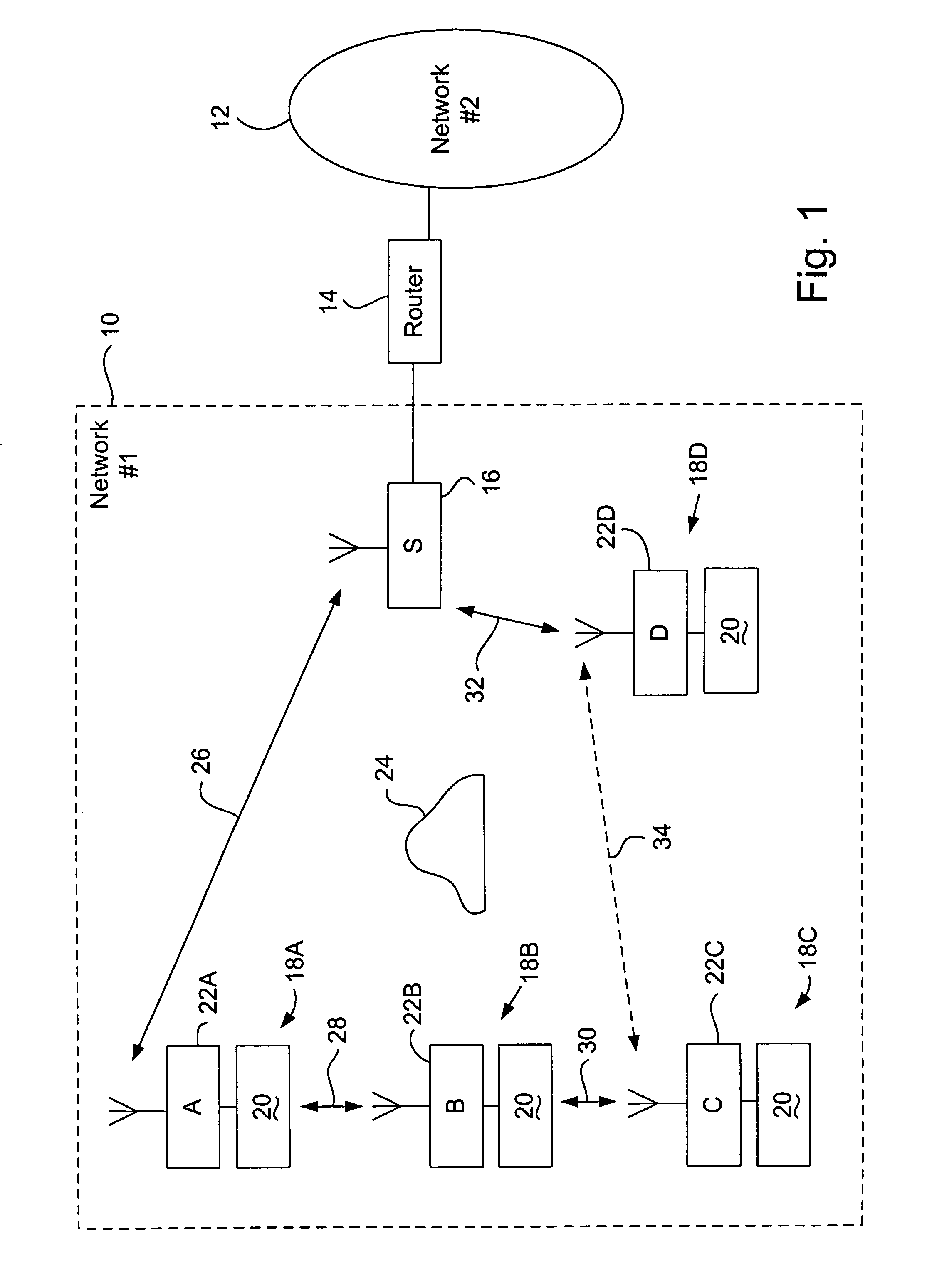
[0064]FIG. 1 illustrates a wireless network system 10 in accordance with the present invention. The wireless network system 10, which will also be referred to herein as a “first network,” is preferably in communication with a second network 12 via a digital communication bridge or router 14. The construction and operation of networks, such as second network 12, and bridges or routers, such as router 14, are well-known to those skilled in the art. It the present invention, it is preferred that the second network operates on the aforementioned TCP / IP protocols, i.e. the second network is the Internet or is a private Intranet. At times, herein, the second network will be referred to as simply the Internet, it being understood that other forms of a second network are also operable with the systems, apparatus, and processes of the present invention. Again, the construction and operation of the Internet and Intranets are well-known to those skilled in the art. Likewise, routers, bridges, ...


PUM


Abstract

A wireless network, which includes a wireless router client operable to broadcast data packets to at least one wireless server and one additional wireless client. Each client and server includes programs for determining optimum routes between them. The client also includes a program for determining if a received data packet is not addressed to it and if the packet has been sent via a new optimal route unknown to the client, and for notifying the respective server of such a new optimal route.

Description

[0001]This application is a continuation of application Ser. No. 09 / 492,933, filed Jan. 27, 2000, now abandoned, which is a continuation of application Ser. No. 08 / 790,894, filed Dec. 6, 1996, now U.S. Pat. No. 6,044,062.TECHNICAL FIELD[0002]This invention relates generally to digital computer networks, and more particularly to wireless digital networks for the transmission of digital data packets.BACKGROUND ART[0003]There are many kinds of networks that can be used to couple computers together for data communication. For example, a simple local area network (LAN), such as a Novell® network or an Appleshare® network, can be used to couple together the personal computers in an office. Often, one or more network “servers” or “hosts” will influence data flow within the network and access to certain network functions such as a central file repository, printer functions, Internet gateways, etc. Other local area networks operate on a peer-to-peer basis without the use of servers.[0004]A w...

Claims


Application Information

Patent Timeline
Patent Type & Authority Patents(United States)
IPC IPC(8): H04J1/16H04L12/28H04L12/56H04L29/06H04W40/02
CPCH04L29/06H04L45/00H04L45/20H04W40/02H04L69/08H04W40/24H04W88/12H04L69/22H04L9/40
Inventor BROWNRIGG, EDWIN B.WILSON, THOMAS W.
Owner IPCO
Learn More