Rotor for dynamo-electric machine
a dynamo-electric machine and rotor technology, which is applied in the direction of dynamo-electric machines, synchronous generators, magnetic circuit shapes/forms/construction, etc., can solve the problems of reducing the cooling effect of the rotor, reducing the cross sectional area of the magnetic path or reducing the void area, and lowering the performance. , to avoid the deterioration of the magnetic circuit, the effect of improving the cooling
- Summary
- Abstract
- Description
- Claims
- Application Information
AI Technical Summary
Benefits of technology
Problems solved by technology
Method used
Image
Examples
first embodiment
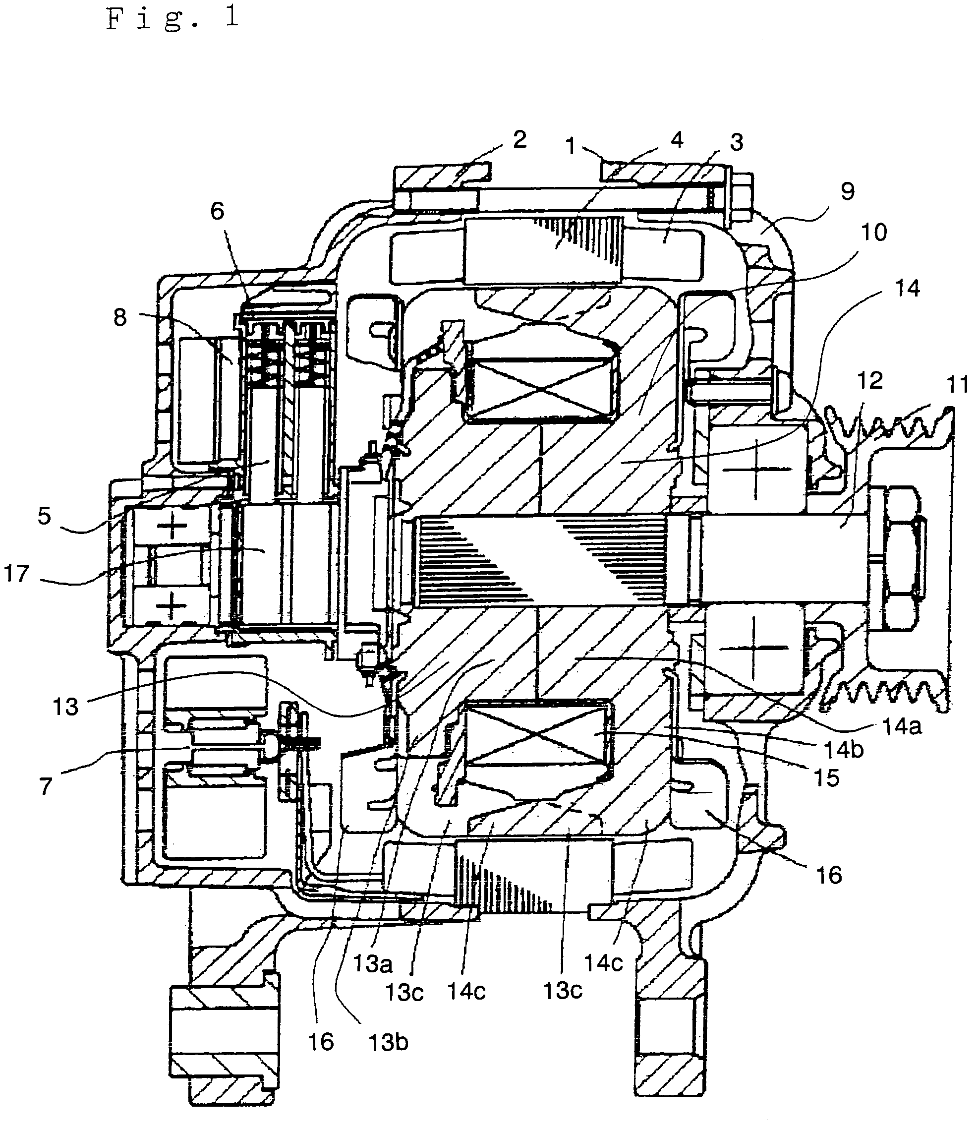
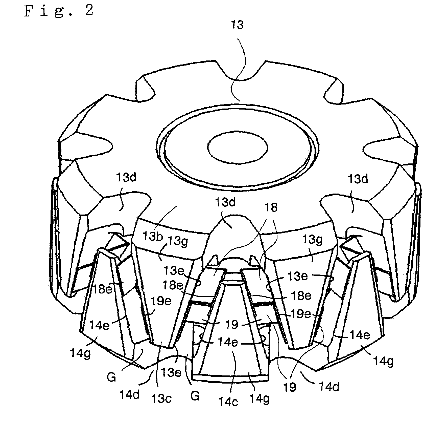
[0028]FIG. 1 to FIG. 3 illustrate a rotor for a dynamo-electric machine according to a first embodiment of the invention. FIG. 1 is a cross-sectional view illustrating a general structure of the dynamo-electric machine, FIG. 2 is a perspective view showing the structure of the rotor, and FIG. 3 is a cross-sectional view of the rotor taken along a plane vertical to the revolving shaft for providing a supplementary explanation of the structure shown in FIG. 2. This dynamo-electric machine is to be used as an alternating current generator for a vehicle, or as a synchronous motor for a vehicle. Typically, this dynamo-electric machine is a Lundel-type alternating current generator.
[0029]A general structure of the dynamo-electric machine will be described below. Referring now to FIG. 1, the dynamo-electric machine includes a front bracket 1 and a rear bracket 2 formed of aluminum, an armature iron core 4 clamped therebetween and having an armature winding 3, a brush retainer 6 provided on...
second embodiment
[0040]FIG. 4 illustrates the rotor for the dynamo-electric machine according to a second embodiment of the invention. In the rotor for the dynamo-electric machine according to this embodiment, the first deformation preventing members 18 are used as the embodiment 1, the second deformation preventing members 19 are eliminated. Each of the first deformation preventing members 18 is attached on the inner wall 13f on each of the magnetic poles 13c. Each of the elongated portions 18e is pressed aginst to the side wall 13e of each magnetic poles 13c. In this arrangement, good assembleability is achieved, and hence productivity is improved. In addition, since required material is reduced, the cost can be reduced. Consequently, a rotor of a dynamo-electric machine in which vibrations of the magnetic poles 13c and 14c are restrained and hence the reduction of the noise is achieved.
third embodiment
[0041]FIG. 5 illustrates the rotor for the dynamo-electric machine according to a third embodiment of the invention. In this third embodiment, each of the first deformation preventing members 18 has a pair of elongated portions 18f and each of the second deformation preventing members 19 has a pair of elongated portions 19f. Each of the elongated portions 18f, 19f is disposed at the center portion of the side gap G and the elongated portions 18f, 19f are combined to each other. Typically, the elongated portions 18f, 19f are pressed to each other at the predetermined pressing force.
[0042]It is also possible to adapt this press so as to change from linear contact at the beginning to surface contact by centrifugal force as the velocity revolution increases, and to mount the deformation preventing members 18 not on the inner wall 13f of the magnetic poles 13c, but on the side walls 13e thereof.
[0043]In this arrangement, the deformation preventing members 18, 19 are pressed to each anoth...
PUM
 Abstract
Description
Claims
Application Information
 - R&D
- Intellectual Property
- Life Sciences
- Materials
- Tech Scout
- Unparalleled Data Quality
- Higher Quality Content
- 60% Fewer Hallucinations
Browse by: Latest US Patents, China's latest patents, Technical Efficacy Thesaurus, Application Domain, Technology Topic, Popular Technical Reports.
© 2025 PatSnap. All rights reserved.Legal|Privacy policy|Modern Slavery Act Transparency Statement|Sitemap|About US| Contact US: help@patsnap.com


