
Contact lenses

a technology of contact lenses and lenses, applied in the field of contact lenses, can solve the problems of eye loss of ability to focus at near distances, sore eyes and headaches, and presbyopic persons with both near vision and distance vision defects

Active Publication Date: 2006-05-30
ALCON INC
View PDF59 Cites 52 Cited by
  • Summary
  • Abstract
  • Description
  • Claims
  • Application Information

AI Technical Summary

Benefits of technology

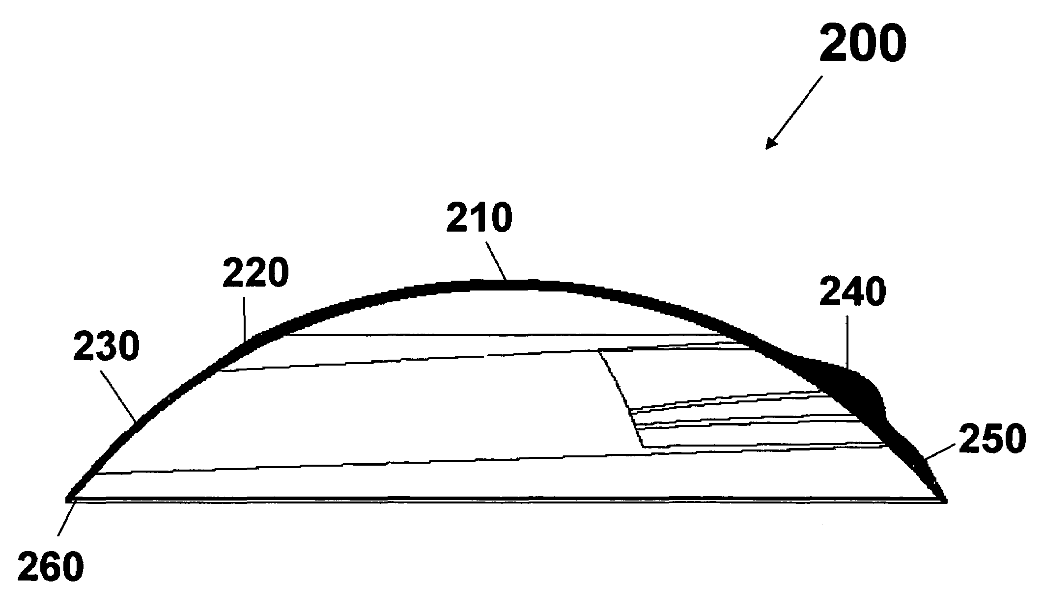
[0014]Another object of the invention is to provide a method for producing a contact lens having an orientation feature which can main

Problems solved by technology

These people may complain of sore eyes and headaches associated with demanding visual tasks.
It is believed that presbyopia occurs as a person ages when the lens of eye loses its elasticity, eventually resulting in the eye losing the ability to focus at near distances (when distance vision is corrected), such as the normal reading distance, and in some cases at intermediate distances.
Some presbyopic persons have both near vision and distance vision defects, requiring simultaneous or alternating vision lenses to properly correct their vision.
The visual performance of the simultaneous vision lens design is limited by its dependence on pupil size.
The consequence of this image degradation is a reduction in visual actuity and / or contrast sensitivity (less signal, more noise), and the quality of the degraded image may or may not be acceptable to the patient.
Therefore, when wearing a simultaneous vision lens, the patient may not be selecting between separate distance and near images.
Moreover, large population of presbyopes also has an astigmatism vision error.
High order aberrations present in an eye can blur images formed on the retina, which can impair vision.
Unlike current contact lenses, customized contact lenses or contact lenses capable of correcting high order aberrations inevitably need to have a complex surface design without restrictions of rotational symmetry.
However, there are some disadvantages associated with designs of contact lenses having prism ballast in the prior art.
Those lenses are not comfortable to wear and / or not highly effective in maintaining lens orientation.
Furthermore, contact lenses with prism ballast as orientation feature may not be able to provide better visual performance since they tend to have optical distortions known as prism.
The lenses with these orientation / stabilization features are not comfortable to wear and / or not highly effective in maintaining lens orientation.

Method used


Image

  • Contact lenses
  • Contact lenses
  • Contact lenses

Examples


Embodiment Construction

[0029]Reference now will be made in detail to the embodiments of the invention. It will be apparent to those skilled in the art that various modifications and variations can be made in the present invention without departing from the scope or spirit of the invention. For instance, features illustrated or described as part of one embodiment, can be used on another embodiment to yield a still further embodiment. Thus, it is intended that the present invention cover such modifications and variations as come within the scope of the appended claims and their equivalents. Other objects, features and aspects of the present invention are disclosed in or are obvious from the following detailed description. It is to be understood by one of ordinary skill in the art that the present discussion is a description of exemplary embodiments only, and is not intended as limiting the broader aspects of the present invention.

[0030]Unless defined otherwise, all technical and scientific terms used herein...


PUM


Abstract

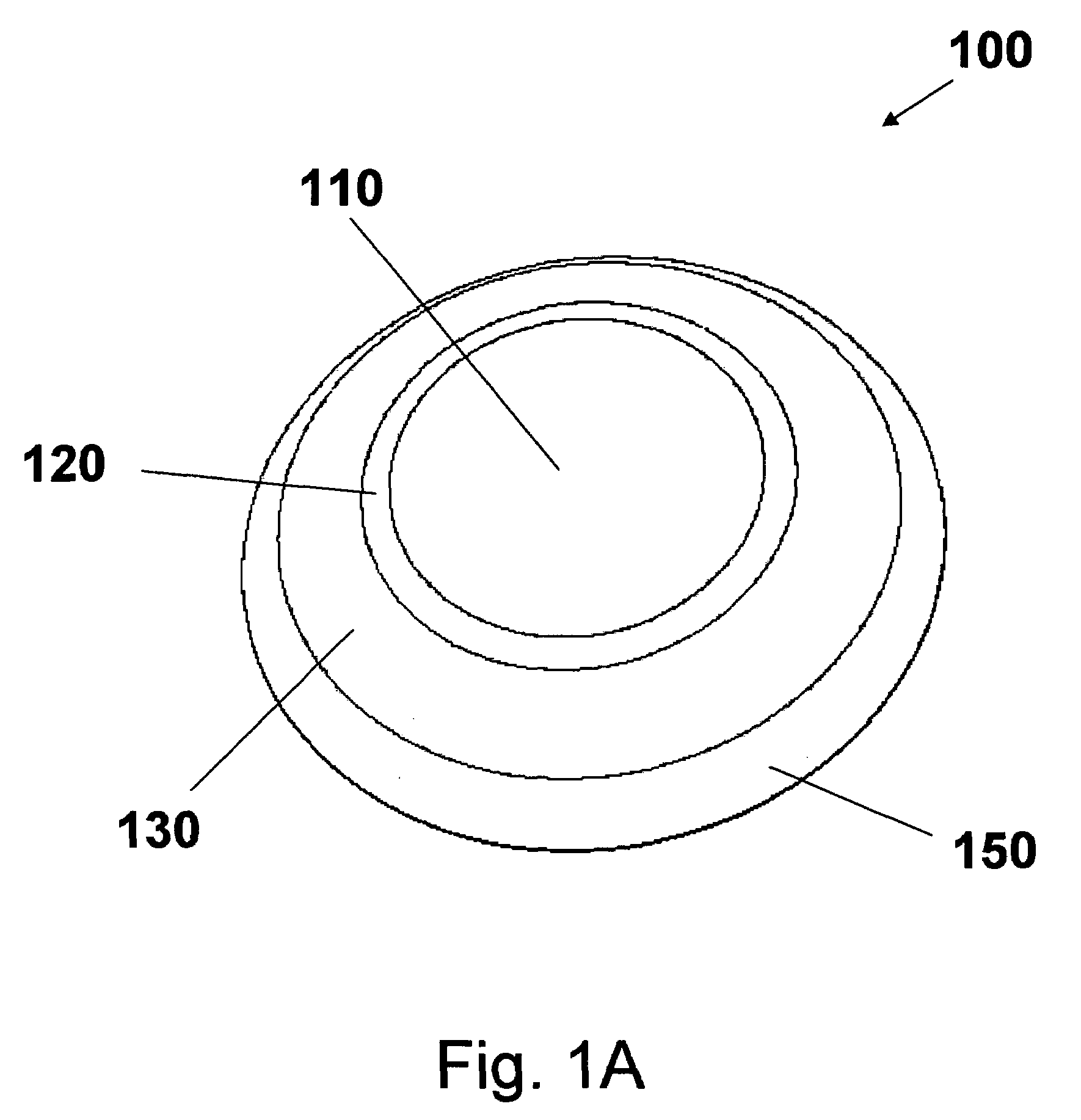
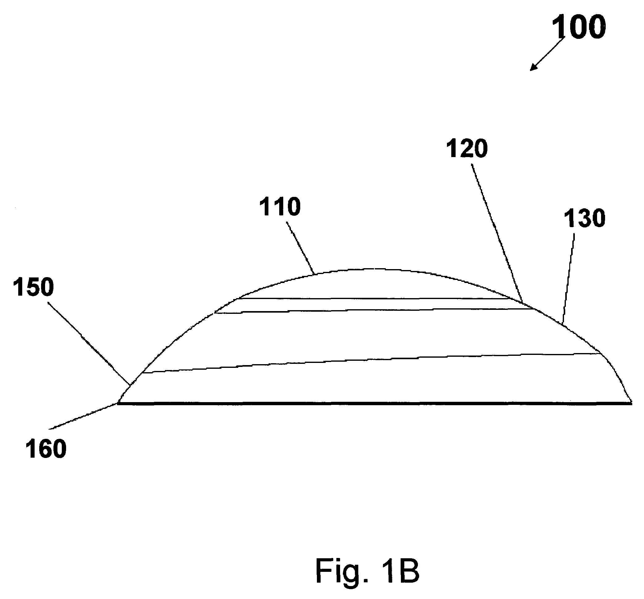
The present invention provides a contact lens having an orientation / stabilization and optionally translation feature that does not provide an prism optical distortion and can effectively maintain a predetermined orientation of the lens on an eye. Like a conventional lens ballast, the orientation feature of the invention works by weighing the lens at its lower half portion, causing it to come to an equilibrium position on the eye. With such orientation feature, the optical zone of the anterior surface can be designed independently to provide an optimal visual performance.

Description

[0001]This application claims the benefit under the benefit under 35 USC § 119 (e) of U.S. provisional application No. 60 / 472,365, filed May 21, 2003, incorporated by reference in its entirety.[0002]This invention is related to contact lenses. In particular, the present invention is related to contact lenses, which require a rotational and / or orientation stability on an eye, such as toric contact lenses, biofocal or multifocal contact lenses, toric multifocal contact lenses, contact lenses capable of correcting high-order wavefront aberrations and the like.BACKGROUND[0003]Contact lenses are widely used for correcting many different types of vision deficiencies. These include defects such as near-sightedness and far-sightedness (myopia and hypermetropia, respectively), astigmatism, and defects in near range vision usually associated with aging (presbyopia).[0004]Astigmatism occurs as the refractive error in an eye is dependent upon meridian. This is usually due to one or more refract...

Claims


Application Information

Patent Timeline
IPC IPC(8): G02C7/04
CPCG02C7/028G02C7/043G02C7/044G02C7/048G02C2202/22G02C2202/04G02C2202/08
Inventor LINDACHER, JOESPH MICHAELMOLINARI, JASON
Owner ALCON INC
Learn More