
Case for portable equipment

Active Publication Date: 2006-05-23
DENSO CORP
View PDF17 Cites 75 Cited by
  • Summary
  • Abstract
  • Description
  • Claims
  • Application Information

AI Technical Summary

Benefits of technology

[0011]According to the invention of this aspect, the decorative film having a transparent base film, to the back surface of which a printed layer having a predetermined print pattern is formed, is disposed to at least a portion of the case so that the front surface of the decorative film is disposed to the most outside surface portion of the case. According to this structure, the printed layer can be protected between the transparent film and the resin base member, so that the predetermined printed pattern of the printed layer can be free from external damage by, for example, a metallic key.
[0023]The body portion may be formed from two half portions so as to have an inner hollow portion when assembled and the operation portion is formed to one of the two half portions. According to this structure, the case can be easily manufactured with a simple forming device.

Problems solved by technology

This coloring method has been considered to be undesirable in an impact in design, and especially, in the case of two-color formation, a fusing (fused) portion, at which the colors are different, provides a weak strength, thus being inconvenient.
In such case, there is a fear that the surface of the portable equipment may be injured by such metal keys and the durability of the portable equipment may be made worse.
Furthermore, in a case of a portable equipment of a type using an electric wave transmission, if the case body is coated with metallic material, the metallic coat film formed on the surface of the case body provides a considerably large thickness, and because of the metal contained in this coat film, permeability or transmission of the electric wave may be deteriorated thereby.

Method used


Image

  • Case for portable equipment
  • Case for portable equipment
  • Case for portable equipment

Examples


first embodiment

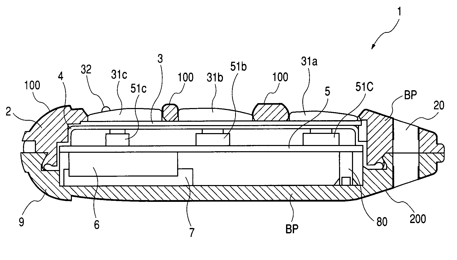
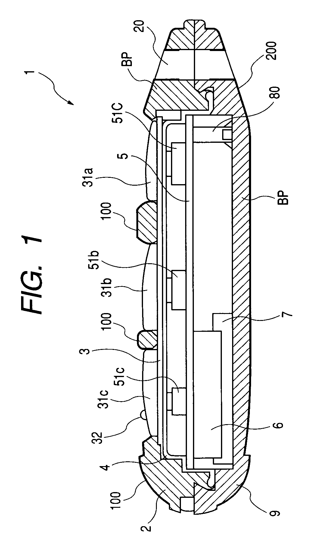
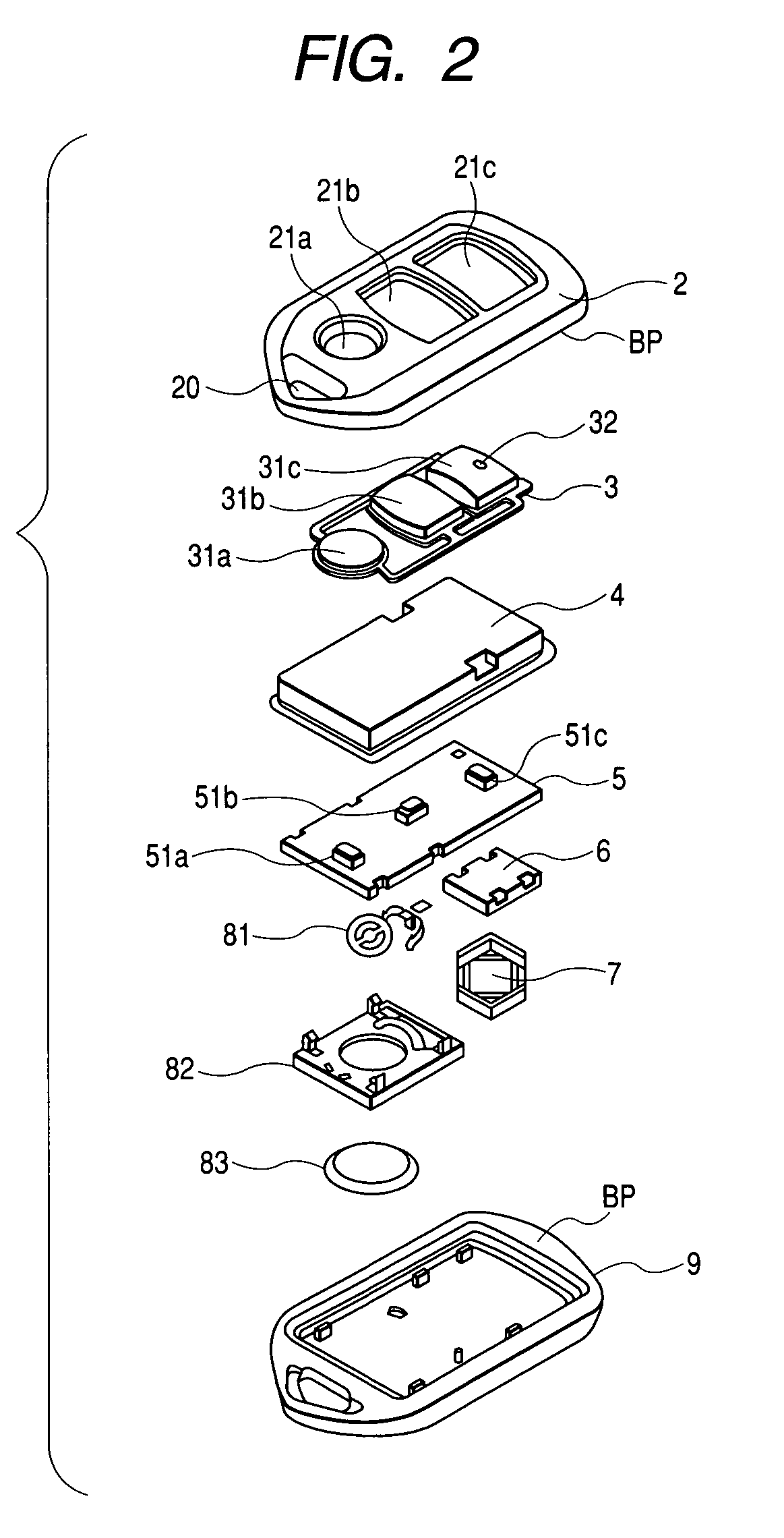
[0043]The first embodiment of the present invention will be first described with reference to FIGS. 1 and 2.

[0044]A portable equipment 1 comprises upper and lower case covers 2 and 9 which constitute an outer case and elements disposed in an inner space defined by the upper and lower case covers 8 and 9 when assembled into the case. As best illustrated in FIG. 2, the elements include: a knob member 3; a water-proof cover 4; a circuit board 5 provided with switching elements 51a to 51c on its upper surface and an antenna element 6 on its lower surface; a cushion member 7 disposed between the antenna element 6 and the lower case cover 9 for damping a shock to the antenna element 6; a cell terminal 81; a cell case 82; a button cell 83; and a spacer 80 supporting the circuit board 5 from the lower case cover 9, in substantially the described order. Further, other circuit elements disposed on the lower surface of the circuit board are omitted from the illustration in FIG. 1.

[0045]Referri...

second embodiment

[0070]In the first embodiment mentioned above, the upper case cover 2 and the lower case cover 9 are formed as independent members, whereas in this second embodiment, both the case covers are formed integrally, and this second embodiment differs from the first embodiment in a structure that two switch knobs are integrally formed to the upper case cover 2. According to this viewpoint, only the upper case cover 2 is explained hereunder through its manufacturing process with reference to FIGS. 10 to 12.

[0071]FIG. 10 is a plan view of a decorative film 400 according to this second embodiment, in which the resin film 101 made of polycarbonate (PC) and having a thickness t=0.3 mm and the transparent protection film 102 made of UV hard coat agent are the same as those in the first embodiment.

[0072]The print (printed or printing) layer 103 includes, as like as in the first embodiment, an metallic printed portion 410, as a body portion, of ink including metallic component and a body color pr...


PUM

PropertyMeasurementUnit
Metallic bondaaaaaaaaaa
Transparencyaaaaaaaaaa

Abstract

A case of a portable equipment for communication to an external system comprises a body portion and an operation portion acting as a function member. At least a portion of the case is provided with a decorative film having a resin film having transparency and a print layer printed on a back surface of the resin film in a predetermined pattern, and a resin base member formed on a back surface of the decorative film so as to contact the print layer. The front surface of the decorative layer is exposed as a most outside surface of the case.

Description

BACKGROUND OF THE INVENTION[0001]The present invention relates to a case for a portable equipment such as transmitter for key-less entry system of a vehicle.[0002]There has been known a key-less entry system as a remotely controllable auxiliary means for a vehicle, which is provided with a portable equipment such as transmitter. The portable equipment is accommodated in a case having a case body generally colored with black. Further, in an event where color changing is effected to the case entirely or partially, the coloring is effected with resin or two-color formation. This coloring method has been considered to be undesirable in an impact in design, and especially, in the case of two-color formation, a fusing (fused) portion, at which the colors are different, provides a weak strength, thus being inconvenient.[0003]Moreover, although as is well seen in a portable phone, for example, a UV coating of metallic color to a surface of the case has been considered, a portable equipment ...

Claims


Application Information

Patent Timeline
IPC IPC(8): G06F1/16E05B19/00B60R16/02B60R16/023E05B49/00G07C9/00H04B1/034H04Q9/00
CPCB60R16/0239Y10T29/49105G07C2009/00968H04Q9/00
Inventor SHIMURA, TOKIONAKAGAWA, MITSURU
Owner DENSO CORP
Learn More