
Dual-band inverted-F antenna with shorted parasitic elements

a parasitic element and inverted antenna technology, applied in the direction of elongated active element feed, resonant antenna, antenna earthing, etc., can solve the problems of poor impedance matching and the conventional inverted-f antenna cannot be operated in a suitable frequency width at 5 ghz band

Inactive Publication Date: 2006-05-23
YAGEO CORP
View PDF4 Cites 85 Cited by
  • Summary
  • Abstract
  • Description
  • Claims
  • Application Information

AI Technical Summary

Benefits of technology

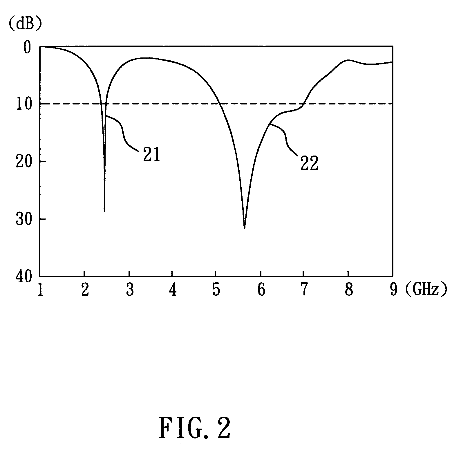
The present invention provides a dual-band inverted-F antenna with shorted parasitic elements that can operate in both the 2.4 GHz and 5 GHz wireless local area network bands. The antenna has a ground plane, two radiating arms, a shorting arm, and a feeding coaxial cable. The length of the radiating arms and the distance between the shorting arm and the first radiating arm can be adjusted to induce extra capacitive reactance to compensate for the inductive reactance caused by the feeding coaxial cable. This allows the antenna to operate in the second band with a 2 GHz frequency width covering the 5 GHz wireless local area network band. The technical effect of this invention is to provide a versatile and efficient antenna for wireless communication in two important frequency ranges.

Problems solved by technology

Because the inductive reactance will increase when the operated frequency increase, the impedance matching is not good at 5 GHz band.
Therefore, the conventional inverted-F antenna can hardly be operated in a suitable frequency width at 5 GHz band.

Method used


Image

  • Dual-band inverted-F antenna with shorted parasitic elements
  • Dual-band inverted-F antenna with shorted parasitic elements
  • Dual-band inverted-F antenna with shorted parasitic elements

Examples


first embodiment

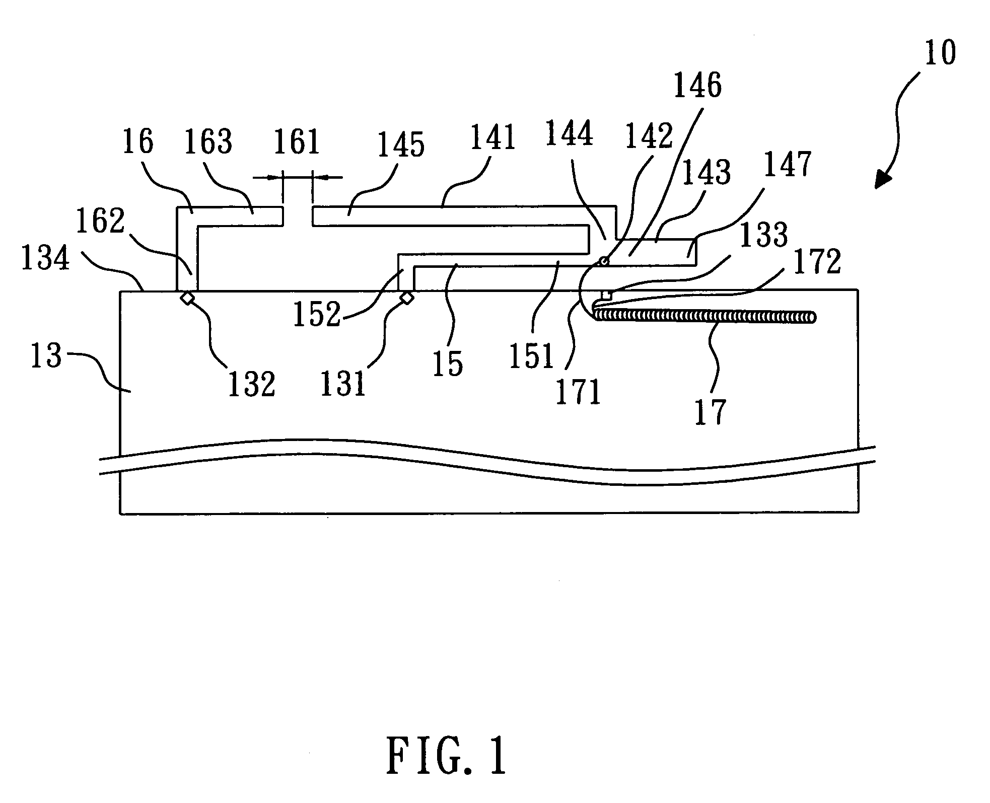
[0015]Referring to FIG. 1, according to the invention, a dual-band inverted-F antenna 10 with shorted parasitic elements comprises: a ground plane 13, a first radiating arm 141, a second radiating arm 143, a shorting arm 15, a shorted parasitic arm 16 and a feeding coaxial cable 17. The ground plane 13 is a metal plane or a metal back plane of a liquid crystal display for a portable computer. The ground plane 13 may be of a rectangular shape. The ground plane 13 has a first short point 131, a second short point 132 and a ground point 133, and the first short point 131, the second short point 132 and the ground point 133 are disposed on an edge 134 of the ground plane 13.

[0016]The first radiating arm 141 is formed in an inverted-L shape and disposed above the edge 134 of the ground plane 13. The first radiating arm 141 has a start terminal 144 and an end terminal 145. The start terminal 144 is vertical to the edge 134 of the ground plane 13, and has a feeding point 142. The end termi...

second embodiment

[0024]Referring to FIG. 3, according to the invention, a dual-band inverted-F antenna 30 with shorted parasitic elements comprises: a ground plane 33, a first radiating arm 341, a second radiating arm 343, a shorting arm 35, a shorted parasitic arm 36 and a feeding coaxial cable 37. The ground plane 33 is a metal plane or a metal back plane of a liquid crystal display for a portable computer. The ground plane 33 may be a rectangular shape. The ground plane 33 has a first short point 331, a second short point 332 and a ground point 333, and the first short point 331, the second short point 332 and the ground point 333 are disposed on an edge 334 of the ground plane 33.

[0025]The first radiating arm 341 is formed in an inverted-L shape and disposed above the edge 334 of the ground plane 33. The first radiating arm 341 has a start terminal 344 and an end terminal 345. The start terminal 344 is vertical to the edge 334 of the ground plane 33, and has a feeding point 342. The end terminal...

third embodiment

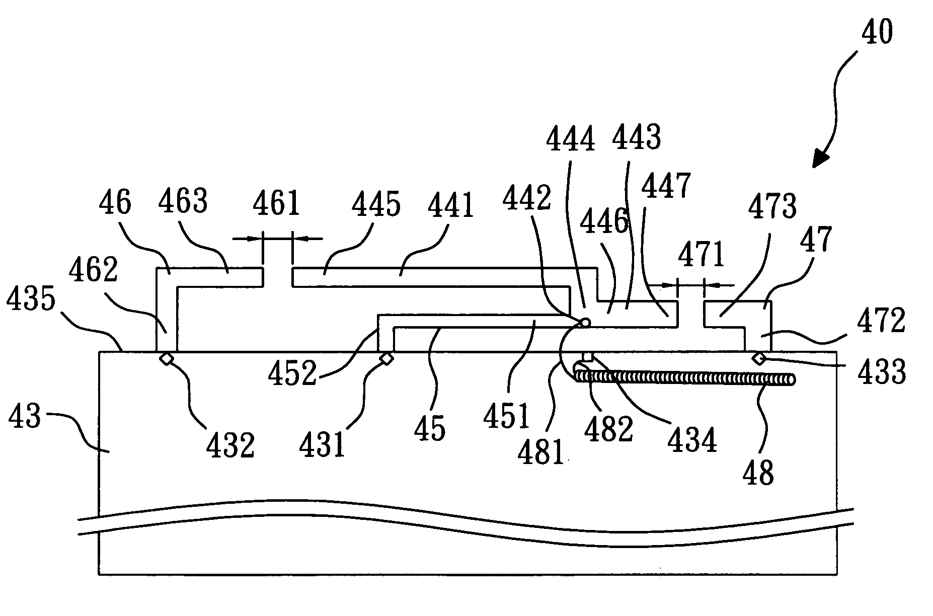
[0032]Referring to FIG. 4, according to the invention, a dual-band inverted-F antenna 40 with shorted parasitic elements comprises: a ground plane 43, a first radiating arm 441, a second radiating arm 443, a shorting arm 45, a first shorted parasitic arm 46, a second shorted parasitic arm 47 and a feeding coaxial cable 48. The ground plane 43 is a metal plane or a metal back plane of a liquid crystal display for a portable computer. The ground plane 43 may be a rectangular shape. The ground plane 43 has a first short point 431, a second short point 432, a third short point 433 and a ground point 434. The first short point 431, the second short point 432, the third short point 433 and the ground point 434 are disposed on an edge 435 of the ground plane 43.

[0033]The first radiating arm 441 is formed in an inverted-L shape and disposed above the edge 435 of the ground plane 43. The first radiating arm 441 has a start terminal 444 and an end terminal 445. The start terminal 444 is verti...


PUM


Abstract

The invention relates to a dual-band inverted-F antenna with shorted parasitic elements. The antenna of the invention comprises a ground plane, a first radiating arm placed above an edge of the ground plane, a second radiating arm placed above the edge of the ground plane, a shorting arm with a substantially inverted-L shape for electrically connecting the first radiating arm and the second radiating arm to the ground plane, a shorted parasitic arm placed above the edge of the ground plane, and a feeding coaxial cable for transmitting signals. There is a distance between the shorted parasitic arm and the first radiating arm so as to induce extra capacitive reactance to compensate the inductive reactance induced by inserting the feeding coaxial cable. The present invention is suitable for the wireless local area network (WLAN) applications in the 2.4 GHz (2.4–2.484 GHz) and 5 GHz (5.15–5.35, 5.725–5.875 GHz) bands.

Description

BACKGROUND OF THE INVENTION[0001]1. Field of the Invention[0002]The present invention relates to a dual-band inverted-F antenna, more particularly, a dual-band inverted-F antenna with shorted parasitic elements.[0003]2. Description of the Related Art[0004]In recent years, wireless communications devices are becoming increasingly popular. The performance of antenna is a key value of the wireless communications devices. The conventional inverted-F antenna can only be operated in a single band of 2.4 GHz or a partial dual-band (including 2.4 GHz and 5.2 GHz or 2.4 GHz and 5.8 GHz). Therefore, the conventional inverted-F antenna cannot be operated totally covering the bands of 2.4 GHz (2.4–2.484 GHz), 5.2 GHz (5.15–5.35 GHz) and 5.8 GHz (5.725–5.875 GHz).[0005]U.S. Pat. No. 6,339,400 B1, entitled “Integrated antenna for laptop application,” discloses an inverted-F antenna disposed on a ground plane of a liquid crystal display for a portable computer. However, the inverted-F antenna can ...

Claims


Application Information

Patent Timeline
Patent Type & Authority Patents(United States)
IPC IPC(8): H01Q1/24H01Q1/12H01Q1/22H01Q9/04H01Q13/10
CPCH01Q1/22H01Q9/42H01Q9/0421H01Q1/2258
Inventor WANG, CHI-YUEHCHUA, BOON-TIONGLEE, CHENG-HAN
Owner YAGEO CORP
Learn More