Camera flash circuit using a piezoelectric transformer to trigger firing of the camera flash tube

a piezoelectric transformer and flash circuit technology, applied in the field of camera flash circuits, can solve the problems of increasing cost and complexity, requiring relatively complex and costly mechanical structure, etc., and achieve the effect of simplifying the changeover and reducing the overall cost of the circui

Inactive Publication Date: 2006-05-23
EASTMAN KODAK CO
View PDF22 Cites 7 Cited by
  • Summary
  • Abstract
  • Description
  • Claims
  • Application Information

AI Technical Summary

Benefits of technology

[0007]An advantage of the present invention is that the piezoelectric transformer may be employed as a substitute for the flash trigger capacitor and step-up trigger transformer in present day commonly used flash circuits without the need added circuit components and without the need for special adaption of the output terminals of the transformer, thereby reducing overall cost of the circuit and simplifying changeover to the new arrangement.
[0008]A further advantage of the invention is that coupling the input of the piezoelectric transformer with the flash capacitor eliminates the need for a separate driving circuit as is required in the aforementioned disclosure of patent U.S. Pat. No. 6,564,015 B2.

Problems solved by technology

While effective, the arrangement requires added relatively complex and costly mechanical structure to actuate the piezoelectric crystal.
However, as shown by the several embodiments in the patent, limitations of the transformer device force the use of added circuit components and / or modification of the transformer output electrode connections with the transformer crystal to achieve the necessary dual functionality thereby adding cost and complexity.

Method used


Image

  • Camera flash circuit using a piezoelectric transformer to trigger firing of the camera flash tube
  • Camera flash circuit using a piezoelectric transformer to trigger firing of the camera flash tube
  • Camera flash circuit using a piezoelectric transformer to trigger firing of the camera flash tube

Examples


Embodiment Construction

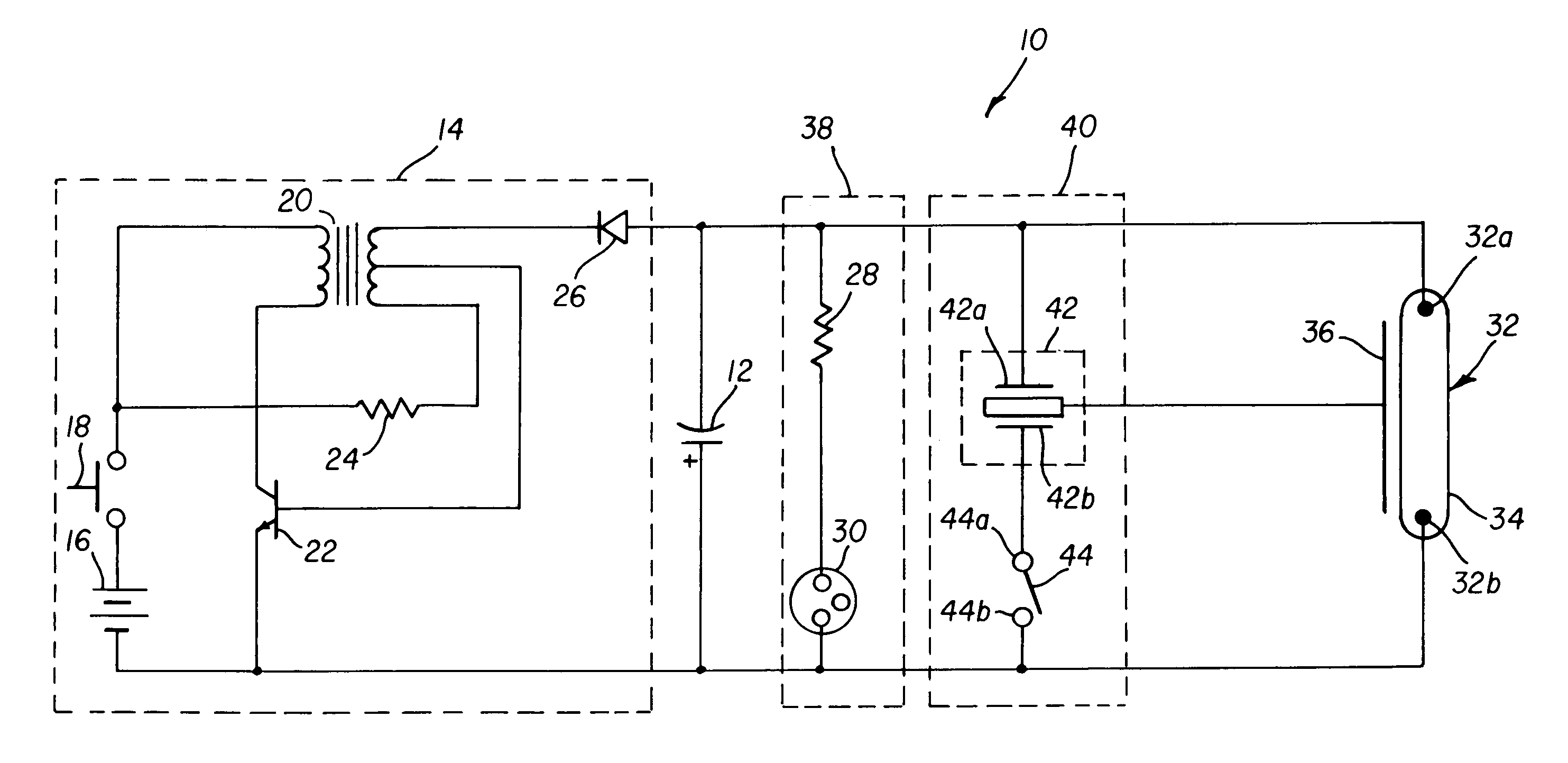
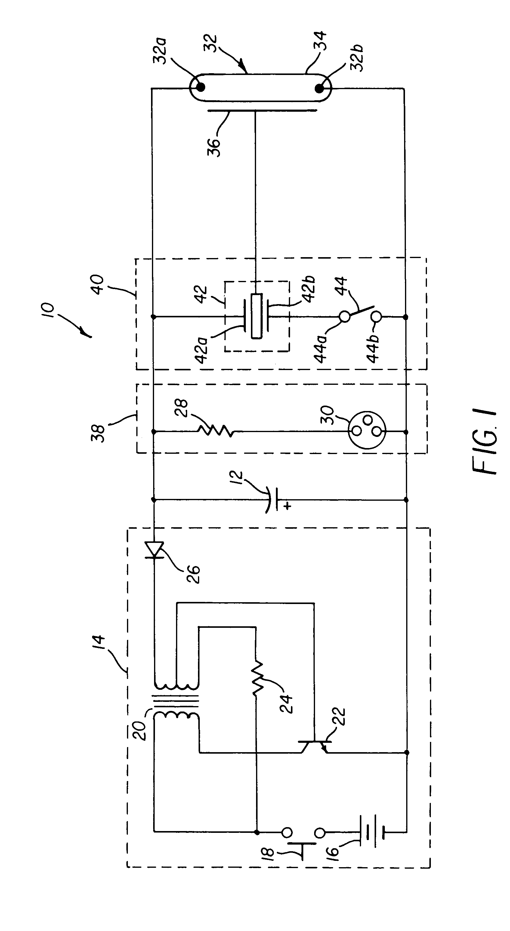
[0011]Turning now to FIG. 1, a camera flash circuit 10 shown therein includes a flash charge storage capacitor 12 and a flash capacitor charging circuit 14 comprised of a battery 16, and a power switch 18, a step-up power transformer 20, an NPN oscillation power transistor 22, and resistor 24. A diode rectifier 26 couples negative-going voltage pulses to storage capacitor 12, to charge the capacitor in known manner, to a negative flash charge voltage of about 330 v. It should be noted that the charging circuit shown is basic in nature and that many well known variations of this basic circuit may be employed. A flash ready indicator circuit 38 is usually provided in the flash circuit and includes resistor 28 and a neon lamp 30. The flash circuit also includes a flash tube 32 having a pair of input electrodes 32a, 32b in an envelope 34 enclosing molecules of an inert gas such as xenon. A flash trigger terminal 36 is mounted adjacent the tube envelope in known manner.

[0012]In accordanc...


PUM


Abstract

A camera flash circuit employing a piezoelectric transformer in the flash trigger circuit, the piezoelectric transformer having input terminals coupled to the main flash voltage storage capacitor and an output terminal coupled to the flash trigger terminal on the flash tube. When the camera flash trigger switch is closed, the input terminals of the piezoelectric transformer are driven directly from the charge voltage stored on the flash storage capacitor to generate the necessary high voltage pulse at the flash tube trigger terminal to initiate firing of the flash tube.

Description

FIELD OF THE INVENTION[0001]This invention relates to camera flash circuits and more particularly to such circuits using a piezoelectric transformer device to ionize gas molecules in the flash tube to thereby initiate firing of the flash tube.BACKGROUND OF THE INVENTION[0002]Flash capable cameras, both film-based and digital electronic, typically employ a flash tube enclosing an ionizable gas, such as xenon, to create the bright flash of light needed to capture images in a low light level scene. Basic elements of a flash circuit used to fire the tube typically include a battery, a voltage converter flash charging circuit, a flash voltage storage capacitor and a trigger circuit connected to a trigger terminal associated with the flash tube. The flash charging circuit converts the low battery voltage of about 1.5 v or 3.0 v to a high flash charge voltage on the order of 330 v. This voltage is applied to the flash storage capacitor which is coupled to the input electrodes of the flash ...

Claims


Application Information

Patent Timeline
Patent Type & Authority Patents(United States)
IPC IPC(8): G03B15/03H05B41/32
CPCH05B41/32
Inventor DOWE, DAVID R.
Owner EASTMAN KODAK CO
Why Eureka
Try Eureka