
Automatic door assembly with video imaging device

Inactive Publication Date: 2006-05-09
STANLEY WORKS THE
View PDF42 Cites 39 Cited by
  • Summary
  • Abstract
  • Description
  • Claims
  • Application Information

AI Technical Summary

Benefits of technology

[0011]The terms internal and external are used with respect to the video data signals to emphasize the fact that the internal signal remains internal to the door assembly and is used by the door controlling system while the external system is output externally of the door assembly to the video device. As a result, the door assembly of the present invention provides the functions and advantages of a video imaging device and the door controlling functions of a typical door assembly into one convenient package. This convenience can be greatly appreciated by establishments that monitor their doorways with video surveillance because the provision of the video imaging device on the door assembly eliminates the need for separately purchasing and installing a video imaging device for monitoring the doorway.
[0014]The assembly of this aspect of the invention is advantageous because the travel area of the door panel can be properly monitored by an imaging device without the costs and complexities associated with continually activating and deactivating multiple sensors as in the prior art arrangements.

Problems solved by technology

In fact, if the door panel is already in the fully open position thereof, the controller may ignore the detection signal and not transmit any door opening signal to save on wear and tear of the operator.

Method used


Image

  • Automatic door assembly with video imaging device
  • Automatic door assembly with video imaging device
  • Automatic door assembly with video imaging device

Examples


Embodiment Construction

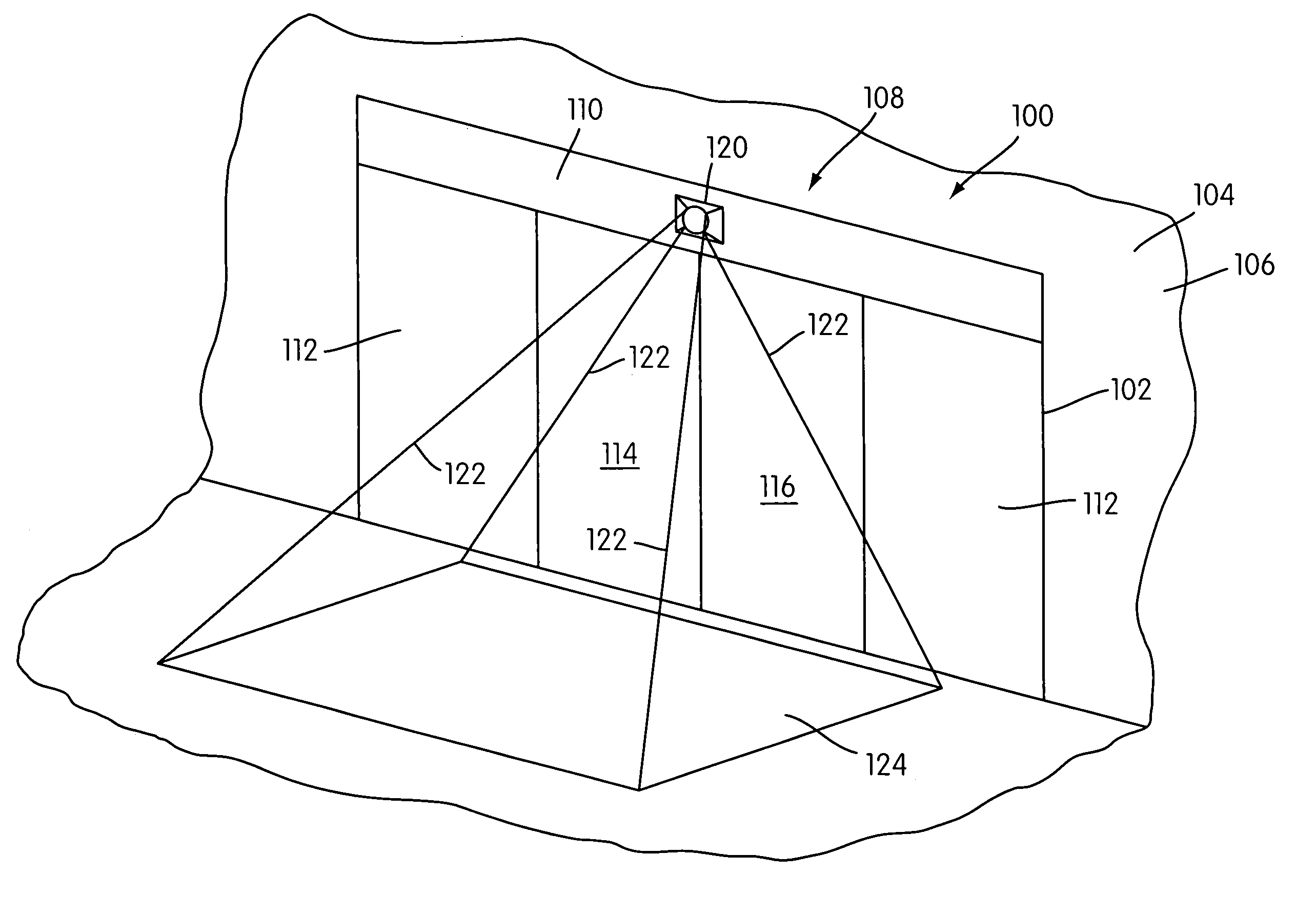
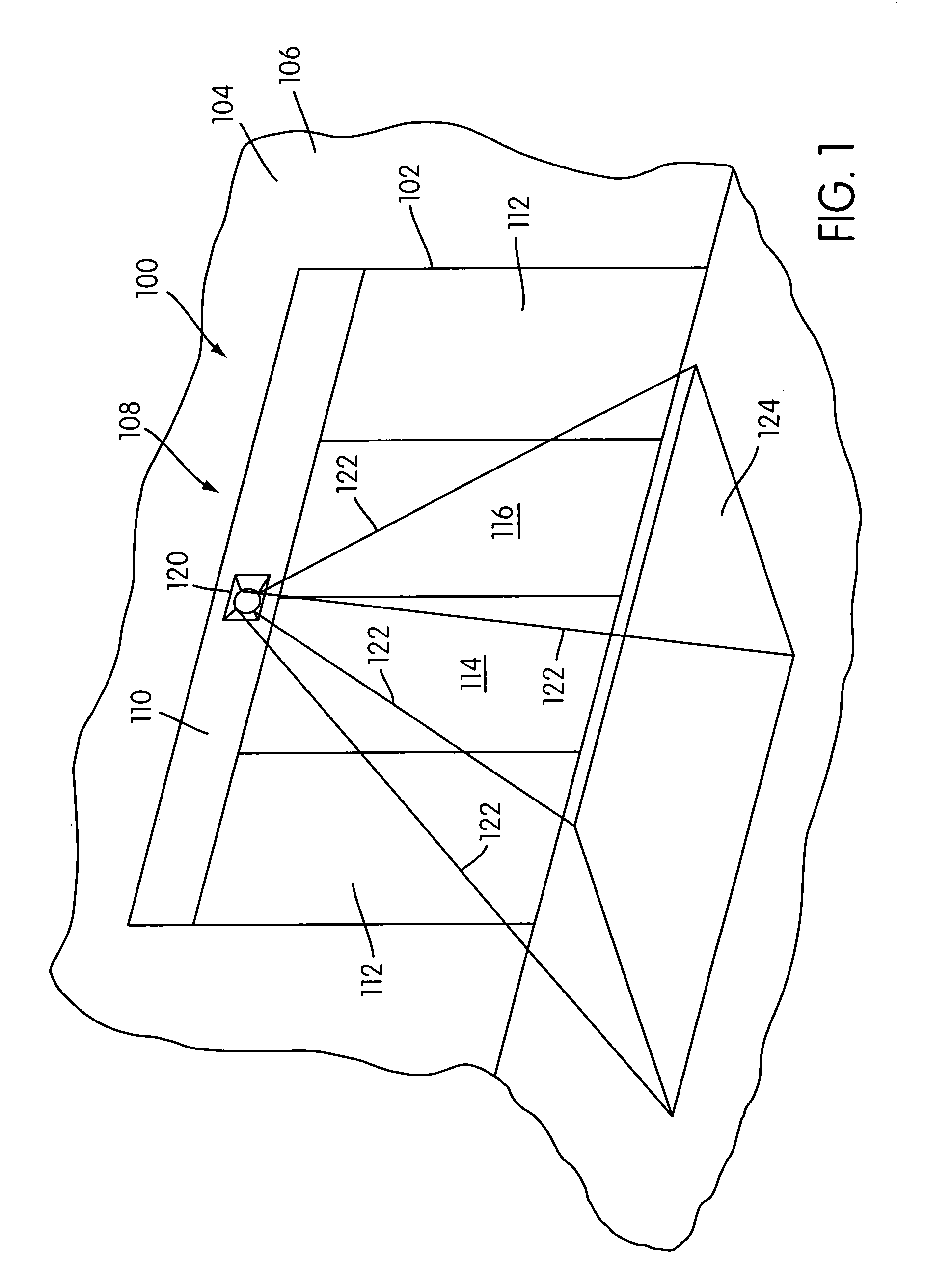
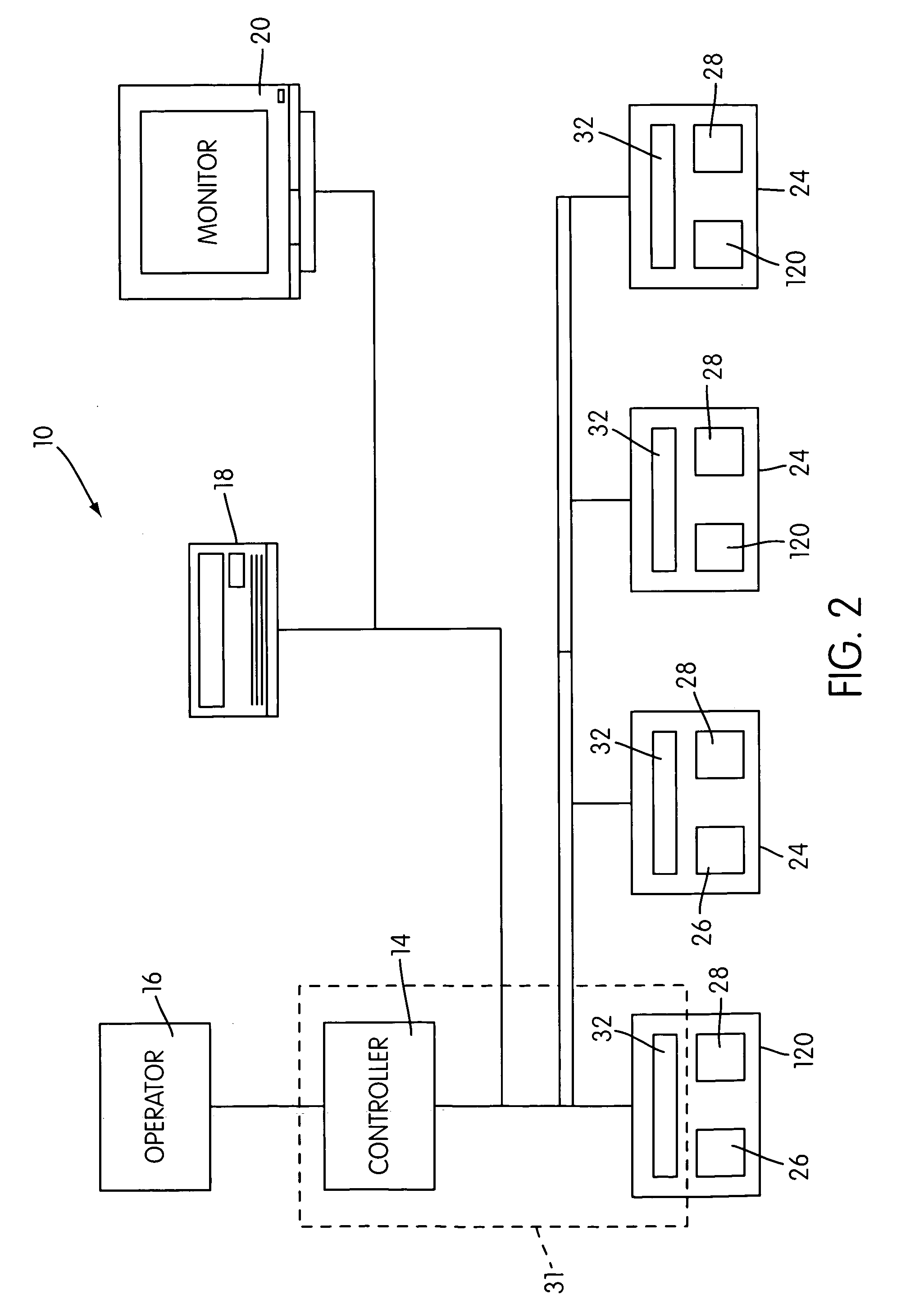
[0021]FIG. 1 is a perspective view of a sliding door assembly, generally indicated at 100, mounted within a doorway 102 of a wall 104 of a building 106, the remainder of the building being cut-away around the doorway 102. The door assembly 100 comprises a frame assembly, generally indicated at 108, that mounts within the doorway 102. The frame assembly 102 comprises a header 110 that houses the door operator (shown schematically at 16 in FIG. 2) and the door controlling system (shown schematically at 10 in FIG. 2) that controls the door operator 16, which system 10 will be described in more detail hereinbelow as being the focus of the present application. The frame assembly 108 also comprises a pair of non-sliding panels 112 that cover opposing sides of the doorway 102.

[0022]The door assembly 100 further comprises door panel structure in the form of a pair of sliding door panels 114, 116 that move rectilinearly between open and closed positions. In the closed position thereof, the d...


PUM


Abstract

An automatic door assembly for installation at a doorway formed through a wall of a building and for use in conjunction with a video device that is (a) capable of receiving a video data signal from a video imaging device monitoring a field of view and (b) processing the video data signal received from the imaging device into a form suitable for displaying images that are visually representative of the imaging device's field of view. The door assembly comprises a frame assembly that mounts to the building wall at the doorway thereof, a door panel that mounts to the frame assembly for movement between closed position and open positions, and a door controlling system. The door controlling system comprises a video imaging device mounted in a viewing position. The imaging device is provided by a digital or analog video camera. In the viewing position, the imaging device monitors a field of view that encompasses an approach area located adjacent to the doorway. The video imaging device transmits an internal video data signal comprising information representative of the field of view. The controlling system also comprises a detection system comprising a video signal processor that communicates with the video imaging device. The processor receives the internal video data signal from the imaging device and processes the information comprising the internal video data signal to determine whether a person or object has entered the approach area. The detection system transmits a door opening signal in response to the processor thereof determining that a person or object has entered the approach area. The door assembly also comprises a door operator connected to the door panel and communicated with the detection system. The door operator moves the door panel from the closed position thereof to the open position thereof responsive to receiving the door opening signal.

Description

[0001]The present application claims priority to U.S. Provisional Application of Spinelli, Ser. No. 60 / 169,977, filed Dec. 10, 1999. The present application also claims priority to U.S. patent application of Spinelli, Ser. No. 09 / 659,463. These applications are hereby incorporated into the present application in their entirety.FIELD OF THE INVENTION[0002]The present invention relates to an automatic door assembly for controlling access through a door opening. More particularly, the present invention relates to an automatic door assembly that incorporates the use of a video imaging device that detects the approach of persons and objects to the door assembly and responsively signals the operator of the door assembly to open the door panel(s) thereof.BACKGROUND OF THE INVENTION[0003]In commercial and industrial buildings, such as, for example, retail stores, factories, warehouses, etc., it is often desirable to provide a video surveillance system to monitor persons and events within th...

Claims


Application Information

Patent Timeline
IPC IPC(8): H04N9/47H04N7/18E05F15/20G01V8/10
CPCH04N7/183H04N7/186E05F15/73E05F2015/767E05Y2900/132
Inventor SPINELLI, VITO A.
Owner STANLEY WORKS THE
Learn More