
Method and system for determining direction of transmission using multi-facet antenna

a multi-facet antenna and antenna technology, applied in the field of network communication, can solve the problems of difficult to provide, inability to gain access to the corporate ethernet network or internet connection, and difficulty in obtaining a communication channel in the wireless network, so as to achieve the effect of reducing power consumption, increasing receiver sensitivity to specific units at known locations, and reducing the distan

Inactive Publication Date: 2006-05-09
CHIGUSA TADAAKI
View PDF74 Cites 37 Cited by
  • Summary
  • Abstract
  • Description
  • Claims
  • Application Information

AI Technical Summary

Benefits of technology

The system enables efficient data transfer with guaranteed quality of service, improved network performance, and enhanced security in dynamic wireless networks, accommodating multiple devices and changing topologies without the need for centralized control.

Problems solved by technology

There is no means of gaining access to the corporate Ethernet network or an Internet connection.
Generally, the quality of a communications channel in a wireless network is not guaranteed so that, for example, a software process executing on a device is not guaranteed a specific transfer rate over any given interval of time.
This makes it very difficult to provide, e.g., streaming media such as video and audio.
Other approaches to wireless communications do not provide a comprehensive system design approach.
Bluetooth does include several features for point-to-point communications between devices, but does this based on a master-slave relationship that is difficult to use in a network with changing topology, such as one made up of mobile wireless transceivers.
This clearly limits the operational range of the network.
These shortcomings include, for example, link inefficiency, security problems, roaming issues and network deployment issues.
This leads to a number of problems in the design of the MAC layer.
The MAC layer also does not generally provide any quality of service functions, since it is not required to by the nature of the communication link.
In addition, in some networks, the MAC layer must sense the radio media before transmission, which means that the best link may not be utilized.
In public cellular systems, the keys are usually generated and stored in a central database, which can lead to security problems with respect to access.
However, these techniques require software to run above the radio connection and must also be run by the user prior to any communication between the user and the network.
However, the problem remains that as the user moves from one BTS to another, the point of attachment to the network changes.
In an IP network, this may mean that the subnet that the user is originally registered on may change thereby leading to loss of connection.
These solutions remain unsatisfactory in that as the user moves around more and more, nodes in the network may become tied up with carrying traffic that is merely transiting the node and not terminating the IP traffic, thereby leading to very inefficient use of network resources.
Some such solutions may attempt to clear up the network trails but may also provide disruption problems for real time traffic.
This can be an expensive and time-consuming process.
Consequently, it is difficult to know the relative location of the two wireless nodes that may wish to communicate.
Hence, it is also difficult to determine a “best path” to the destination or recipient node without generally flooding the network with route requests the essentially search every possible path for a route to the destination.
The foregoing method of establishing links between two wireless nodes is very inefficient, wasting a large amount of bandwidth in the process.
In addition, the foregoing method also limits the number of nodes that could be supported.
In effect, the network becomes self-limiting because of the lack of node location information.
Use of GPS, however, is generally quite expensive in terms of product cost and power drain on each node.
In addition, GPS has certain coverage limitations which prevent it from being used in some physical locations, such as, inside a building structure.

Method used


Image

  • Method and system for determining direction of transmission using multi-facet antenna
  • Method and system for determining direction of transmission using multi-facet antenna
  • Method and system for determining direction of transmission using multi-facet antenna

Examples


Embodiment Construction

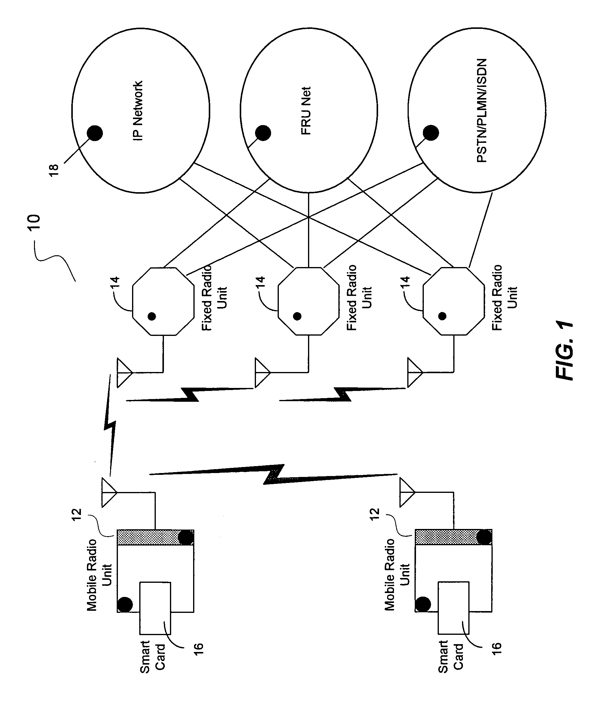
[0040]The present invention in the form of one or more exemplary embodiments will now be described. FIG. 1 is a simplified schematic block diagram illustrating one exemplary embodiment of the present invention. In this exemplary embodiment, the network 10 includes a number of mobile radio units (each an MRU) 12 and a number of semi-fixed or fixed radio units 14 (each an FRU). Based on the disclosure and teachings provided herein, a person of ordinary skill in the art will appreciate that other types of devices that are able to send and receive signals, i.e., transceivers, can be used as MRUs or FRUs in accordance with the present invention.

[0041]In one exemplary embodiment, the MRU 12 is a user portable device that is capable of handling wireless communications. The MRU 12 includes two types of high bandwidth radio, one is used for long range relay communication and the other for shorter range local communication. The MRU 12 is capable of communicating with nearby MRUs and FRUs 14. ...


PUM


Abstract

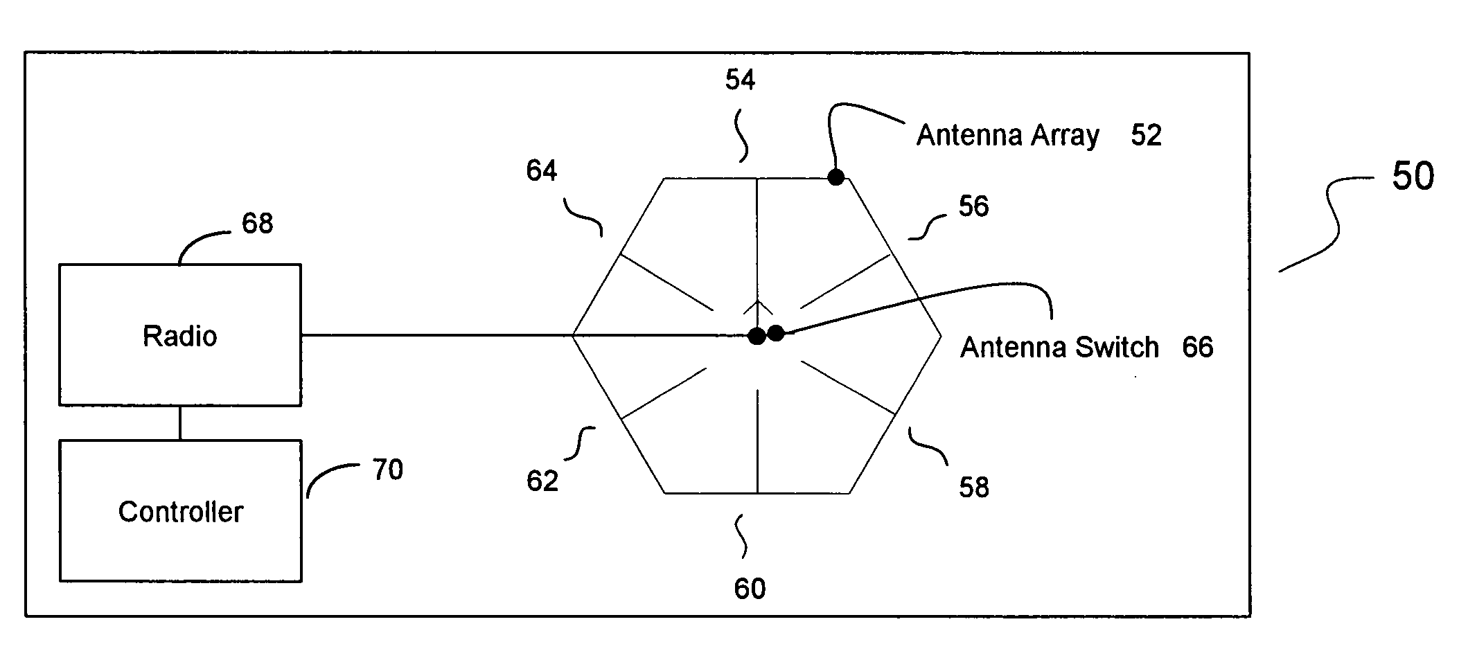
A method for determining direction of transmission using an antenna array having a number of panels is disclosed. Each panel is configured to receive signals. According to one aspect of the method, each of the panels is directed to receive signals from a transmitting node. For each panel, a first table having data representing received signal power difference between the panel and a first neighboring panel and a second table having data representing received signal power difference between the panel and a second neighboring panel are built. The panel with the maximum received power is identified. For the identified panel, a first gain table and a second gain table corresponding to its first and second neighboring panels are searched to identify a first transmission angle and a second transmission angle, if any. A transmission angle relative to the transmitting node is determined using the first and second transmission angles.

Description

CROSS-REFERENCES TO RELATED APPLICATION(S)[0001]The present application claims the benefit of priority under 35 U.S.C. § 119 from U.S. Provisional Patent Application Ser. No. 60 / 403,786 entitled “SYSTEM FOR MOBILE BROADBAND NETWORKING USING DYNAMIC QUALITY OF SERVICE PROVISIONING”, filed on Aug. 14, 2002, the disclosure of which is hereby incorporated by reference in its entirety for all purposes.BACKGROUND OF THE INVENTION[0002]The present invention relates in general to network communications and, more specifically, to a method and system for providing an active routing antenna for use in conjunction with fixed and mobile wireless transceivers with dynamic routing based on quality-of-service (QoS) criteria in order to optimize data transfers in a network with dynamically changing topology.[0003]Wireless networks are gaining in popularity. Standards such as IEEE 802.11a, 802.11b, 802.1 μg, Bluetooth, Ultra Wideband (UWB), etc., allow users to connect wirelessly via portions of the ...

Claims


Application Information

Patent Timeline
Patent Type & Authority Patents(United States)
IPC IPC(8): G01S5/04
CPCG01S3/18H01Q21/205H04B7/0868H04B7/0686H04B7/0491
Inventor SAYERS, IAN
Owner CHIGUSA TADAAKI
Learn More