
Removing natural gas liquids from a gaseous natural gas stream

Active Publication Date: 2006-05-09
SHELL OIL CO
View PDF9 Cites 9 Cited by
  • Summary
  • Abstract
  • Description
  • Claims
  • Application Information

AI Technical Summary

Benefits of technology

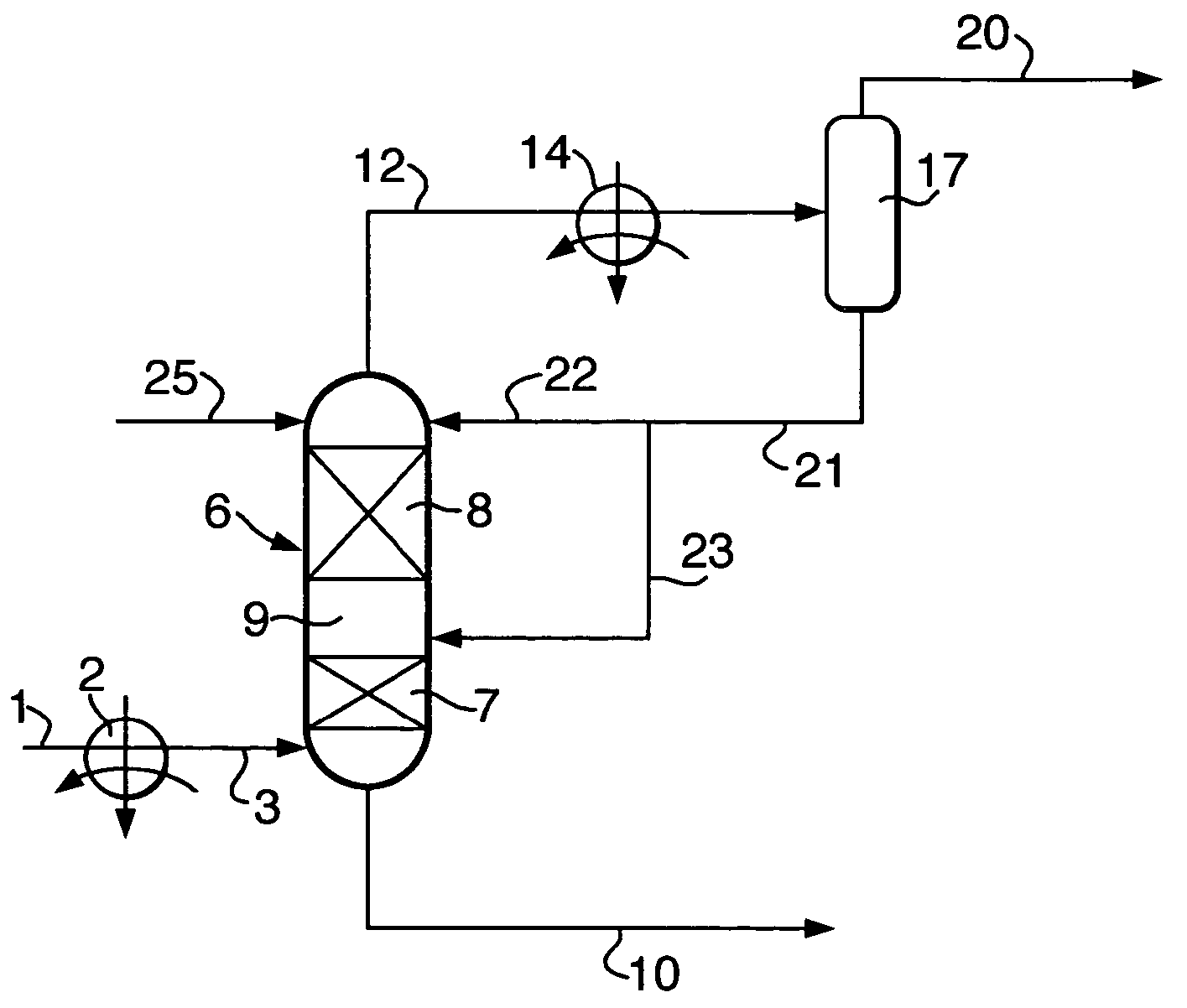
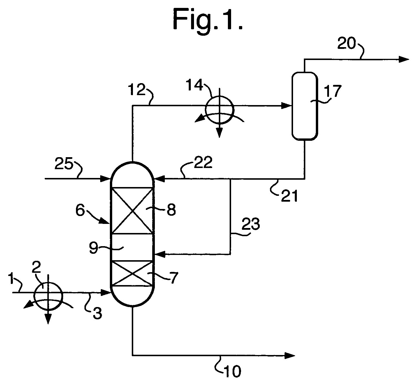
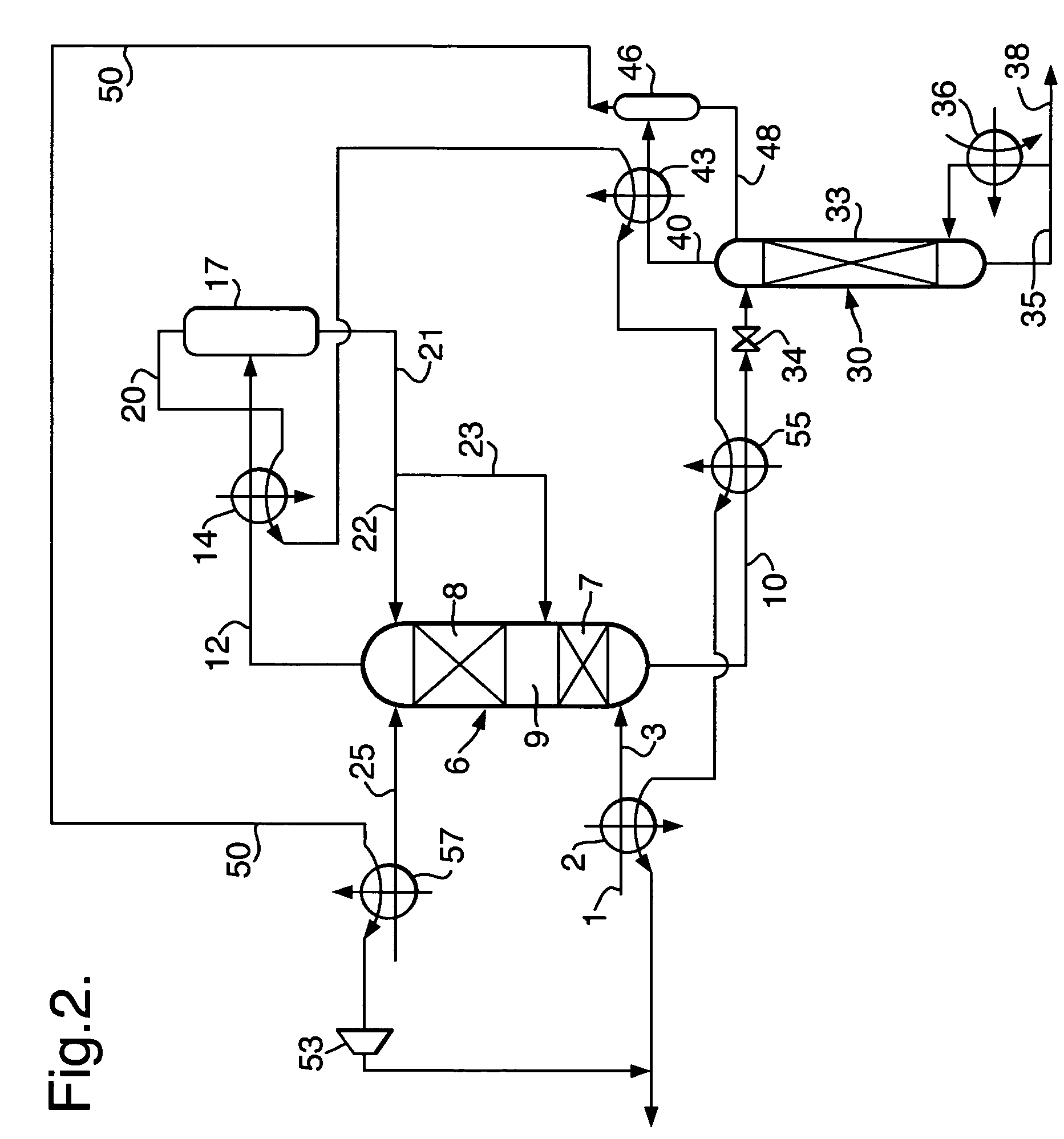
[0025]A method for removing natural gas liquids from a gaseous natural gas stream is provided wherein high-pressure separation is obtained, which has a high propane recovery and a high rejection of methane and ethane. Moreover the process provides a method of removing natural gas liquids in which no reboiler is needed.

Problems solved by technology

However, the overhead product still contains considerable amounts of ethane, propane and butanes.

Method used


Image

  • Removing natural gas liquids from a gaseous natural gas stream
  • Removing natural gas liquids from a gaseous natural gas stream
  • Removing natural gas liquids from a gaseous natural gas stream

Examples


Embodiment Construction

[0021]In the specification and the claims the term natural gas liquids is used to refer to heavier hydrocarbons, such as liquefied petroleum gas components and natural gasolines.

[0022]The natural gas liquids are removed, because they have an economic value and because removing the natural gas liquids reduces the heating value of the natural gas stream.

[0023]By way of example we give a molar composition of a natural gas stream from which the natural gas liquids are to be removed: methane 86 mol %, ethane 6 mol %, propane 4 mol %, butane plus 1 mol %, and the balance is formed by other components, such nitrogen, carbon dioxide and helium.

[0024]The present invention relates in one aspect to removing such natural gas liquids from a natural gas stream at elevated pressure, for example at pressures greater than 3 MPa (absolute) and less than the critical pressure of the natural gas, which is about 7 MPa (absolute).

[0025]A method for removing natural gas liquids from a gaseous natural gas ...


PUM

PropertyMeasurementUnit
Fractionaaaaaaaaaa
Pressureaaaaaaaaaa
Heataaaaaaaaaa

Abstract

Process for removing natural gas liquids from a gaseous natural gas stream at elevated pressure to obtain a gaseous product stream having a reduced content of natural gas liquids is provided.

Description

[0001]The present invention relates to removing natural gas liquids from a gaseous natural gas stream.BACKGROUND OF THE INVENTION[0002]U.S. Pat. No. 5,325,673 publication describes a method of pre-treating a natural gas stream for liquefaction by removing heavier hydrocarbons from it, comprising the steps of:[0003]a) introducing a natural gas feed stream into a scrub column having upper enriching and lower stripping sections;[0004]b) contacting the feed stream with a liquid reflux stream introduced into the upper enriching section of the column to absorb C5+ hydrocarbons from the feed stream;[0005]c) recovering an overhead vapour product containing C2–C4 hydrocarbons and having a concentration of less than about 1 ppm C6+ hydrocarbons;[0006]d) reboiling a portion of liquid in the lower section of the column to strip lighter hydrocarbons from the feed stream;[0007]e) recovering a liquid bottom product enriched in C5+ hydrocarbons; and[0008]f) operating the column to obtain the C2–C4 ...

Claims


Application Information

Patent Timeline
IPC IPC(8): B01D53/14F25J3/06F25J3/02
CPCB01D53/14F25J3/0209F25J3/0233F25J3/0238F25J3/0242F25J2245/02F25J2200/04F25J2200/70F25J2200/74F25J2205/50F25J2230/60F25J2200/02F25J2205/30F25J3/02F25J3/0223
Inventor BRAS, EDUARD COENRAADKUMAR, PARAMASIVAM SENTHIL
Owner SHELL OIL CO
Learn More