
Perilaryngeal oral airway with flexible tip guide

a technology of oral airway and flexible tip guide, which is applied in the field of medical devices, can solve the problems of literally life-threatening, death can quickly ensue, and the mask ventilation cannot be successfully achieved, so as to facilitate positive pressure ventilation, shorten the length of the housing, and ensure the patient's comfort.

Inactive Publication Date: 2006-05-09
ENGINEERED MEDICAL SYST
View PDF78 Cites 49 Cited by
  • Summary
  • Abstract
  • Description
  • Claims
  • Application Information

AI Technical Summary

Benefits of technology

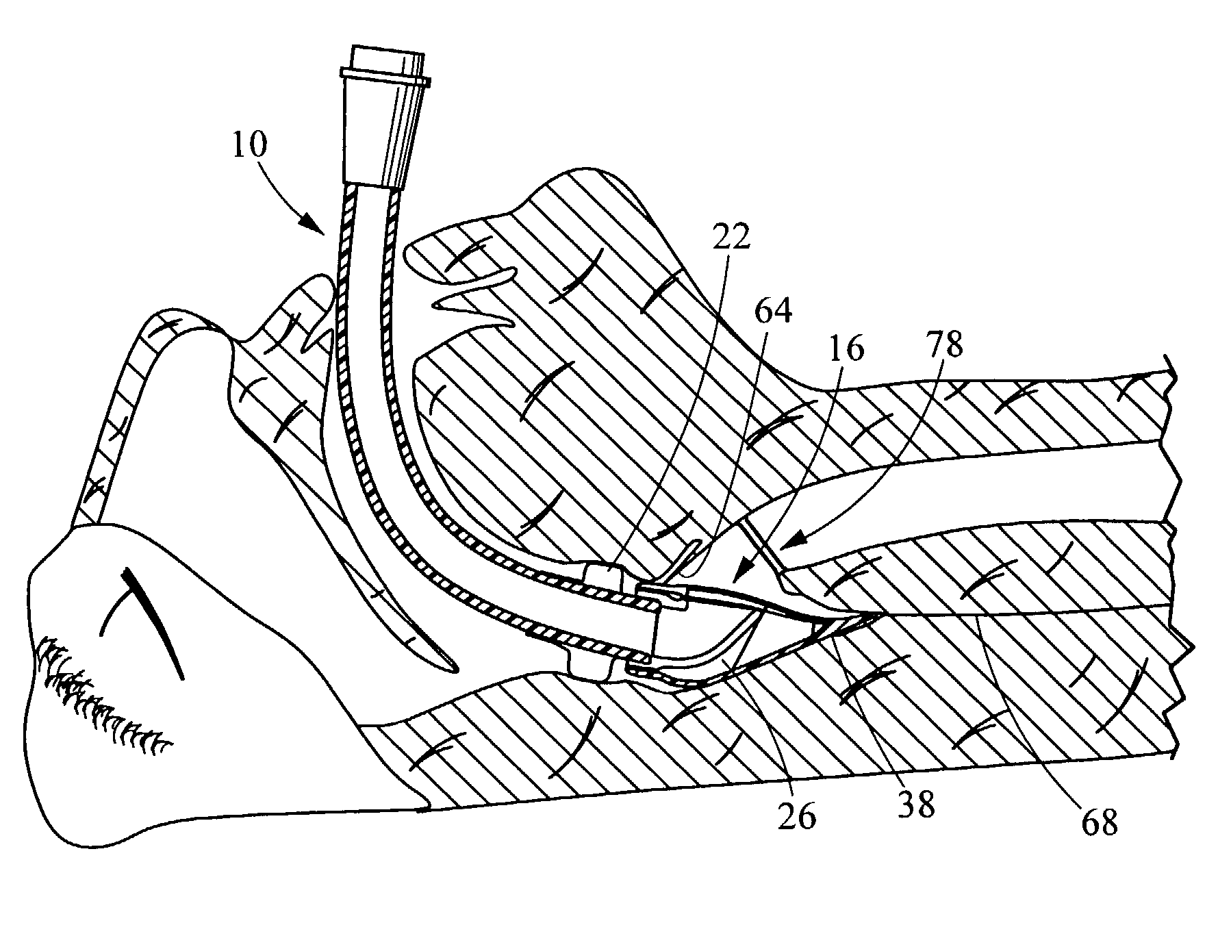
[0021]The present invention provides an oral airway for reliably holding soft tissue structures away from the laryngeal opening to assure adequate airflow to a patient. The invention also provides a supraglottic airway which holds soft tissues in the vicinity of the laryngeal opening apart and which provides for seating of the distal end of the oral airway in a consistent and precise manner adjacent the larynx or glottis aperture for facilitating positive pressure ventilation by anesthesia circuit, resuscitation mask or ventilator. The present invention further provides a flexible leading tip that is configured to bend toward the larynx as the airway is inserted into the mouth and pharynx of a patient. This allows the tip to function as a guide facilitating proper placement of the device within a patient. Moreover, because the tip is flexible and the housing itself is flexible in that they can bend in the direction of the larynx, the bending effectively shortens the length of the housing as it makes the critical bend into the pharynx, thereby minimizing trauma to the contacted tissue. The flexible tip is further configured to lodge on the esophagus side of the arytenoid cartilage which helps position the opening of the airway proximate the laryngeal opening. These many advantages are provided by a structure which is rigid enough to assure proper placement and to prevent inadvertent kinking of the airway, yet soft enough to minimize the risk of injury to the sensitive tissue of the oral cavity, pharynx and hypopharynx. The flexible breathing tube can be manipulated by an operating surgeon to displace it from the operating field within an oral cavity or pharynx. The ultra-thin walled cuff of the present invention allows providing a single-sized cuff that can effectively form a seal in the pharynx or hypopharynx of a patient, regardless of the patient's size or anatomy. Finally, all these many advantages are provided by an airway which is relatively easily manufactured from inexpensive materials, thereby promoting its widespread use and making its many advantages readily available.

Problems solved by technology

However, in some patients, no matter what physical adjustments are made or the particular oral airway which is inserted, mask ventilation cannot be successfully achieved.
Such cases are literally life-threatening as hypoxemia and death can quickly ensue if the patient's blood is deprived of oxygen due to a lack of ventilation.
Most significantly, soft tissue structures in the hypopharynx (the area between where conventional oral airways end and the glottis opens into the trachea) collapse inwardly and obstruct airflow.
Unfortunately, all oral airways which have been introduced into practice to date end bluntly well above the epiglottis (the cartilaginous structure just above the glottis or laryngeal opening) and glottis and thus place patients at risk for significant airway obstruction.
Another mechanism of airway obstruction which occurs while using oral airways is the patient having large lips covering the outside opening of the oral airway with subsequent inadequate airflow through the nasal passages (due to the solid posterior wall of the airway limiting passage of air into the airway at the level of the nasopharynx).
As a result, the distal end (i.e., the end which first enters the mouth and passes down into the pharynx of the patient) often bruises or otherwise damages soft mucosal surfaces of the patient during insertion or once the oral airway has been seated in place.
For this reason, the Baildon oral airway suffers from the problems discussed above in that it fails to provide any structure to prevent the collapse of soft tissue structures in the hypopharynx.
However, the airway of Moses likewise suffers from the problems discussed in detail above in that the blunt-shaped end terminates well above the glottis, thereby allowing possible soft tissue obstruction to occur.
Moreover, the device of Augustine functions as a guide for placing an endotracheal tube in a “blind” manner and is neither designed for nor could it possibly function to allow mask ventilation to be carried out.
While providing a seal with which to administer positive pressure ventilation, there are several potential problems when using an LMA.
First, the device is easily malpositioned so that ventilation is not possible, for example, by virtue of the epiglottis bending back over the glottis and thereby obstructing air flow.
Second, by directly covering the glottic aperture, trauma to the glottic structures (arytenoid cartilages, vocal cords) can occur.
In addition, the cost of this product (over $200) becomes a factor when limitations to reuse occur due to physical damage of the device or accidental loss.
Third, as a reusable product, the hazard of cross-contamination from one patient to another cannot be completely eliminated.
However, this device has several significant limitations which prevent it from functioning adequately.
First, the airway suffers from the problems of those previously discussed in that it ends well above the glottis, thereby allowing soft tissue obstruction to impair the flow of oxygen to the lungs.
Second, with the cuff placed so far proximally in the oro-pharynx, the device tends to push itself out of the patient's mouth, thereby requiring that the device be secured in place by means of a strap placed around the patient's head.
This, of course, makes positive pressure ventilation impossible in those patients.
These devices end well above the glottic opening and thus function poorly in terms of reliably directing the end of an endotracheal tube into the glottis with blind passage.
As a result, the hard distal end of the endotracheal tube may be directed against the structures which surround the glottic opening (arytenoid, cuneiform and corniculate cartilages, epiglottis, aryepiglottic folds) and cause damage to these structures or their soft tissue surfaces.
Further, that damage may result in hemorrhage which obscures vision if subsequent placement of the endotracheal tube by means of a fiberoptic device is attempted.
However, these structures have hard advancing surfaces which can likewise cause trauma.
However, in addition to sharing the above discussed problems common to all LMA's, this device relies on precise positioning so that a movable flap raises an obstructing epiglottis out of the way of an advancing endotracheal tube.
However, LMA's occupy a somewhat variable and inconsistent position within the hypopharynx in relation to the precise anatomic location of the glottis (due to anatomic variability among patients as well as the distensible nature of the proximal epiglottis and hypopharynx where it resides).
As a result, blind intubation with an endotracheal tube with this device can also result in tissue trauma by virtue of its advancing end being misdirected.
Known oral airways are too rigid to allow the airway to be moved from the surgical field.
Further, a version of the LMA which is made using a flexible reinforced breathing channel suffers from the limitations common to LMAs discussed above.
Another problem with known airway devices, including LMA's, is the difficultly that can be encountered in inserting the device into the mouth and pharynx of a patient.
Executing this turn with known devices can be difficult and can cause damage to the soft mucosal tissue that makes up the posterior surface of the pharynx as it is engaged by the airway device.
First, it is intended to be a stiff structure which increases the risk of harm to soft tissue it contacts.
Finally, while FIG. 2 of the Pagan patent shows a preformed bend in the leading tip, this bend is actually opposite the direction of the larynx as the device is inserted into the pharynx of a patient and thus does not effective guide the LMA while minimizing patient trauma.

Method used


Image

  • Perilaryngeal oral airway with flexible tip guide
  • Perilaryngeal oral airway with flexible tip guide
  • Perilaryngeal oral airway with flexible tip guide

Examples


Embodiment Construction

[0036]The perilaryngeal oral airway described herein is a preferred embodiment of a perilaryngeal oral airway structure including a flexible tip for guiding insertion of the perilaryngeal oral airway into the mouth and pharynx of a patient. Further alternative structures of perilaryngeal oral airways are disclosed in Applicant's co-pending application Ser. No. 09 / 409,295, now U.S. Pat. No. 6,386,199, the contents of which are incorporated herein in their entirety by reference. It should be appreciated by those skilled in the art that the perilaryngeal oral airway structures disclosed in U.S. Pat. No. 6,386,199, could be modified to include the flexible tip feature described herein.

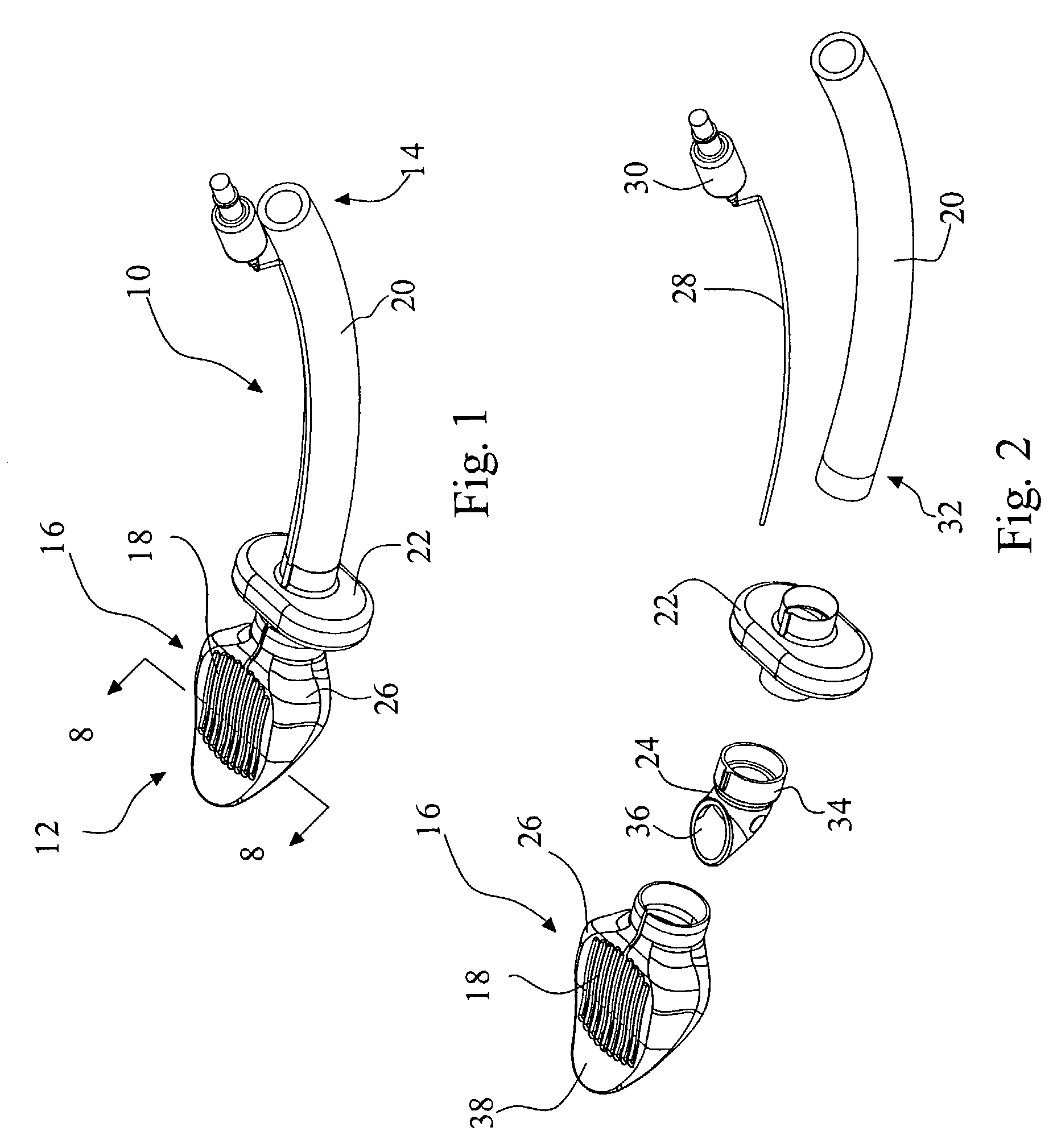
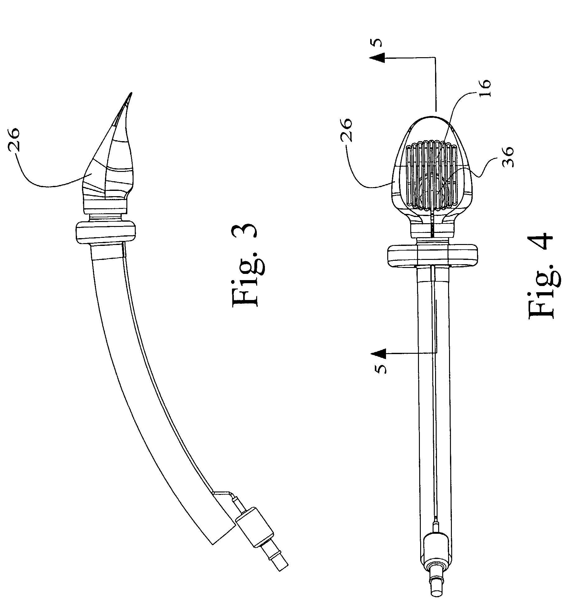
[0037]A perilaryngeal oral airway (“PLA”) 10 is shown in an assembled perspective view in FIG. 1. The PLA can generally be described as an elongate tubular member having a distal end 12 and a proximal end 14. An opening 16 is provided on an anterior portion of the distal end and a number of flexible bars 1...


PUM


Abstract

An oral airway consists of an elongate tubular member having a leading distal end and a proximal end, the leading distal end leading the elongate tubular member as it is inserted into the mouth and pharynx of a patient. An opening at the leading distal end of the elongate tubular member is inclined so that a posterior portion of the distal portion extends beyond an anterior portion of the distal end. A flexible tip portion extends distally beyond the opening to aid in insertion of the oral airway into the mouth and pharynx of a patient. The tip is configured to flex toward the opening as it abuts tissue within the mouth and pharynx of a patient.

Description

TECHNICAL FIELD[0001]The present invention relates generally to a class of medical devices commonly referred to as oral airways and supraglottic airways which are inserted through a patient's mouth and into the patient's pharynx while the patient is undergoing general anesthesia or is undergoing respiratory treatment such as is carried out with cardiopulmonary resuscitation. More specifically, the present invention is directed to a perilaryngeal oral airway and perilaryngeal supraglottic airway which is capable of acting as an endotracheal tube guide and which seats deep in a patient's hypopharynx to prevent the soft tissue of the glottis and epiglottis from obstructing the airway.BACKGROUND ART[0002]Oral airways were introduced into the practice of anesthesia and cardiopulmonary resuscitation several decades ago for two basic purposes. First, they prevent the patient's biting down on and occlusion of a previously placed oral endotracheal tube. Second, and most important, oral airwa...

Claims


Application Information

Patent Timeline
Patent Type & Authority Patents(United States)
IPC IPC(8): A61M16/00A61M16/04
CPCA61M16/0409A61M16/04A61M16/0443
Inventor ALFERY, DAVID D.QUINN, BRAD
Owner ENGINEERED MEDICAL SYST
Learn More