Projection zoom lens

Inactive Publication Date: 2006-05-02
ASIA OPTICAL INT LTD
View PDF5 Cites 13 Cited by
  • Summary
  • Abstract
  • Description
  • Claims
  • Application Information

AI Technical Summary

Benefits of technology

[0009]Accordingly, an object of the present invention is to provide a compact projection zoom lens effectively eliminating aberrations and improving the projection image quality.
[0010]Another object of the present invention is to provide a projection optical system having a projection zoom lens, which has a compact structure and can obtain a high-quality image.
[0011]A further object of the present invention is to provide an image-taking optical system having a projection zoom lens, which has a compact structure and can obtain a high-quality image.
[0024]By zooming the projection zoom lens from the wide-angle end to the telephoto end, the first lens group moves toward the object side, and the second lens group moves toward the image side, and the distance between the first and the second lens groups is shortened.
[0028]In comparison with the prior art, the projection zoom lens according to the present invention has a compact structure because of employing the first lens group of negative refractive power and the second lens group of positive refractive power. Moreover, since the present projection zoom lens satisfies seven requisite conditions, all the aberrations can be excellently corrected, and the projection image quality is greatly improved.

Problems solved by technology

Although the conditional projection zoom lens effectively reduces aberrations and improves the quality of a projected image, it is not fit for use in projectors because an optical system employing the four-group zoom lens will be bulky, and the manufacturing cost thereof will be increased and the assembly thereof will be complicated.
However, this patent only roughly introduces the configuration and the function of the two-group movable lens, and does not provide any detailed description of conditions and parameters necessary to the design.

Method used


Image

  • Projection zoom lens
  • Projection zoom lens
  • Projection zoom lens

Examples


Embodiment Construction

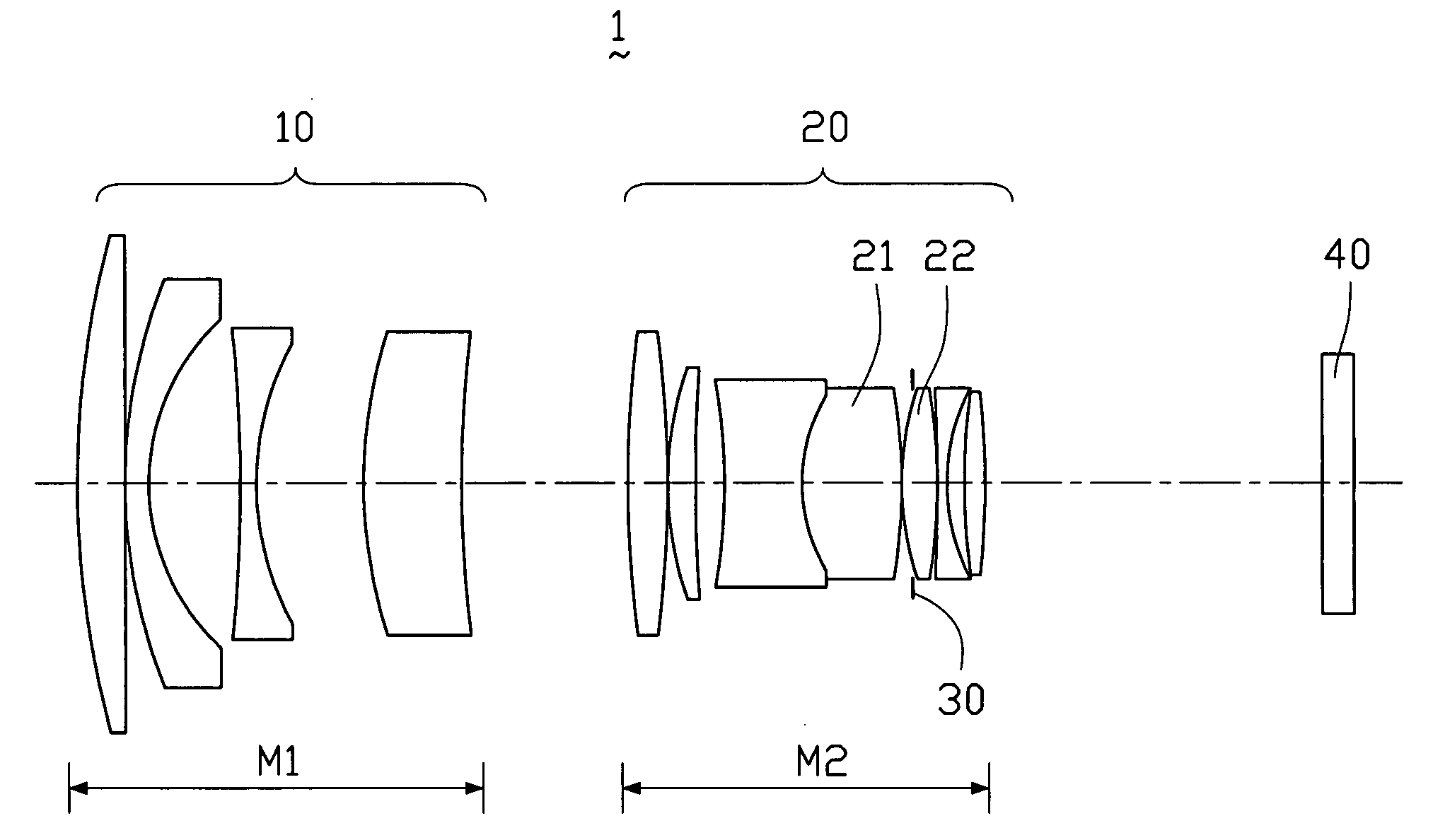
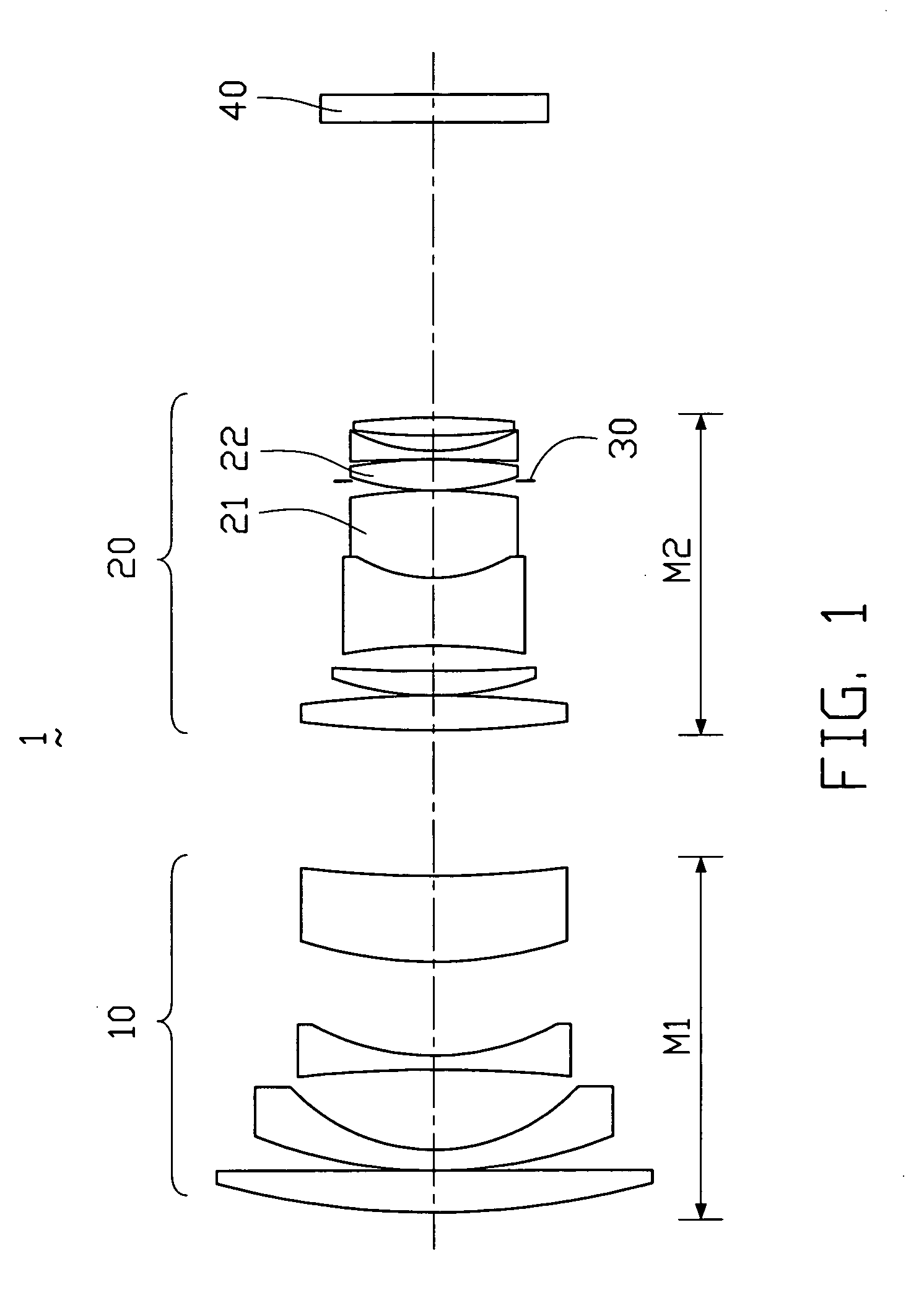
[0042]FIGS. 1, 5 and 9 respectively show projection zoom lenses 1, 1′, and 1″ in accordance with first, second and third embodiments of the present invention. The projection zoom lenses 1, 1′, and 1″ of the present invention all can be assembled on a DLP projector and can be used for projecting an image formed on an image-forming device (such as a DMD modulator) to a large screen.

[0043]The projection zoom lens 1 shown in FIG. 1 comprises, in order from a screen side (the left side as viewed in FIG. 1) to an image plane side (the right side as viewed in FIG. 1), a first lens group 10 having a negative refractive power, and a second lens group 20 having a positive refractive power. The first lens group 10 consists of a plurality of lens elements, which are movable along an optical axis of the projection zoom lens 1 within a first variable distance M1. The second lens group 20 consists of a plurality of lens elements, which are movable along the optical axis within a second variable di...


PUM


Abstract

A projection zoom lens includes, from an image side to an object side, a first lens group having a negative refractive power, consisting of a number of lens elements and being movable along the optical axis of the projection zoom lens; a second lens group having a positive refractive power, consisting of a number of lens elements and being movable along the optical axis of the projection zoom lens; and an aperture stop arranged between two lens elements of the second lens group and being axially movable therewith.

Description

BACKGROUND OF THE INVENTION[0001]1. Field of the Invention[0002]The present invention relates to a projection zoom lens, and more particularly to a projection zoom lens for use in a projection optical system of a projector and also use in an image-taking optical system of an image-taking device.[0003]2. Description of the Prior Art[0004]Projectors, such as a CRT (Cathode Ray Tube) projector, an LCD (Liquid Crystal Display) projector, a DLP (Digital Light Processing) projector, and an LCoS (Liquid Crystal on Silicon) projector, can project an image or other information on a large screen. For example, a projection optical system of the DLP projector uses a DMD (Digital Micro-mirror Device) modulator as a light valve, wherein minute mirror-surface elements (micro-mirrors) are arranged in an array corresponding to pixels and form an image by controlling the angles of the respective mirror-surfaces, and a projection zoom lens enlarges said image to be displayed on the large screen.[0005]...

Claims


Application Information

Patent Timeline
IPC IPC(8): G02B15/14G02B9/00
CPCG02B15/177G02B15/1425
Inventor KUO, CHUNG-YUAN
Owner ASIA OPTICAL INT LTD
Why Eureka
Try Eureka