
Sensor doppler/wavelet processing

a technology of doppler and wavelet, applied in the field of sensors, can solve the problems of clutter in most radar systems, large target returns of clutter, and the effect of clutter

Inactive Publication Date: 2006-05-02
LOCKHEED MARTIN CORP
View PDF2 Cites 18 Cited by
  • Summary
  • Abstract
  • Description
  • Claims
  • Application Information

AI Technical Summary

Benefits of technology

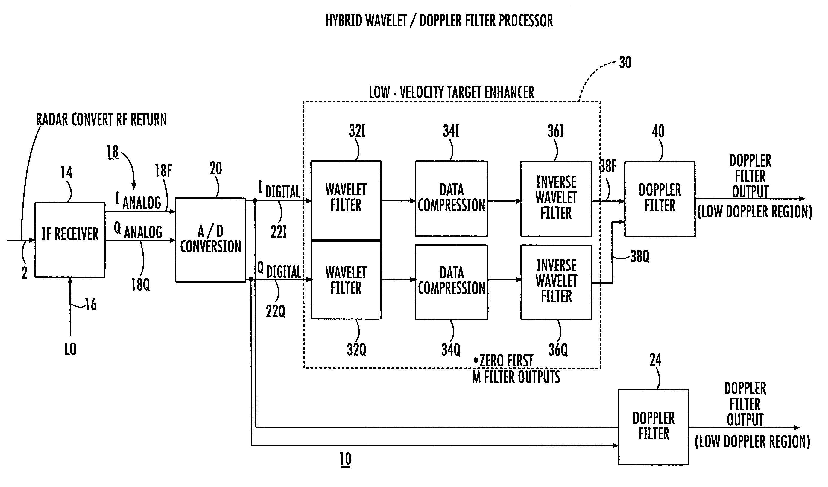
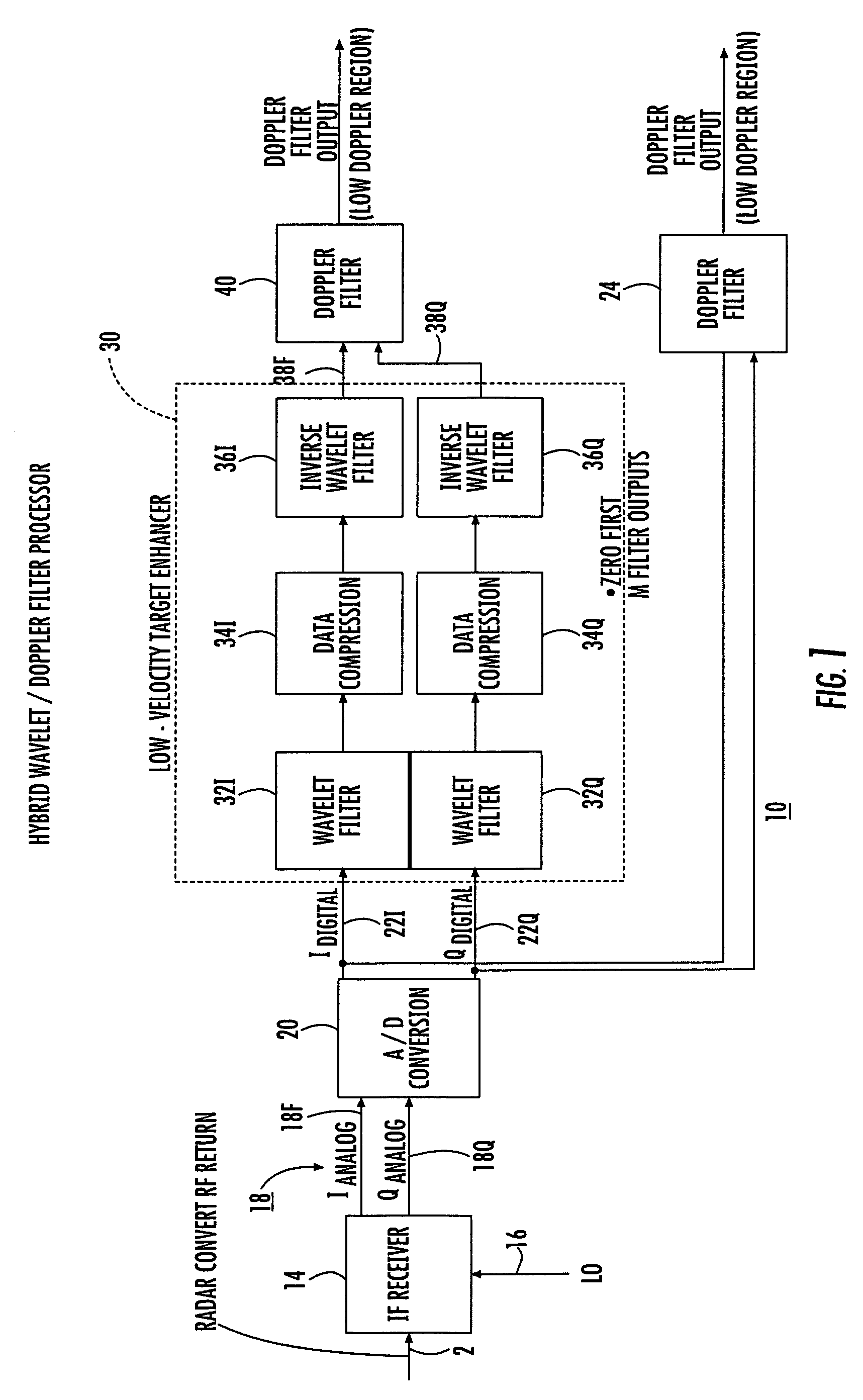
[0006]A method according to an aspect of the invention is for filtering coherent multipulse radar return signals. The method comprises the steps of separating the return signals into mutually orthogonal I and Q components, performing wavelet processing on the I component to generate an I wavelet filter output, and performing wavelet processing on the Q component to generate a Q wavelet filter output. The I and Q wavelet filter-outputs are data compressed to remove those portions which are most likely to contain clutter, to thereby generate data compressed wavelet filter outputs. An inverse wavelet filtering function is performed on the compressed wavelet filter outputs, to thereby generate edited coherent I and Q components. Doppler filtering, which may be in the form of the discrete Fourier transform or the fast Fourier transform (DFT or FFT), is performed on the edited coherent I and Q components to thereby generate frequency-domain target data in which the minimum discernible target velocity is improved.

Problems solved by technology

One of the problems to which most radar systems are subject is that of clutter.
Clutter is caused by undesired targets, such as trees in a land-based system or waves in a maritime system, which undesired targets are relatively near the radar system, or otherwise located so as to generate an undesired radar return signal.
A concomitant is that nearby clutter will produce target returns which are very much greater than the returns from small or inconspicuous targets at substantial range.
Clutter can occur at any range, however, and tends to obscure desired targets at that range.
Unfortunately, slow-moving targets, such as helicopters, which are near the radar system, may have return signals which are near the locations in which clutter occurs, and may have target velocities which are low or in the same range as that of clutter.
Doppler filtering is not fully effective in extracting target information under such conditions.

Method used


Image

  • Sensor doppler/wavelet processing
  • Sensor doppler/wavelet processing

Examples


Embodiment Construction

[0010]FIG. 1 is a simplified block diagram of a portion of a radar receiver according to an aspect of the invention. In FIG. 1, radar return signals resulting from target reflections due to coherent transmitted pulses appear on an input signals path 12, and are applied to an intermediate-frequency (IF) receiver 14. Receiver 14 also receives local oscillator signals by way of a path 16, and produces analog inphase (I) and quadrature (Q) baseband signals, which are applied by way of individual path portions 18I and 18Q of a path 18 to an analog-to-digital converter (ADC) 20. ADC 20 converts the analog I and Q signals to digital form, and the resulting digital I and Q signals appear on paths 22I and 22Q, respectively.

[0011]The digital I and Q signals are applied to a first Doppler filter bank 24, which is a conventional Doppler filter bank for filtering the return signals into various frequency bins. It should be noted that the term “Doppler filter bank” is meant to include all manifes...


PUM


Abstract

A method according to an aspect of the invention is for filtering coherent multipulse radar, sonar or lidar returns. The method comprises the steps of separating the returns into mutually orthogonal I & Q components, performing wavelet processing on the I and Q components to generate an I & Q wavelet filter output. The I & Q wavelet filter outputs are data compressed to remove clutter portions. Data compression may be removal of large-amplitude or earliest wavelet responses. An inverse wavelet filtering function is performed on the compressed wavelet filter outputs, to thereby generate edited coherent I & Q components. Doppler filtering, is performed on the edited coherent I and Q components to thereby generate frequency-domain target data in which the minimum discernible target velocity is improved.

Description

FIELD OF THE INVENTION[0001]This invention relates to sensors such as radar, sonar, and lidar, using a combination of wavelet and Doppler processing to enhance resolution of relatively low-speed targets in the presence of clutter.BACKGROUND OF THE INVENTION[0002]In radar (or sonar or lidar) processing to identify targets, the radar signals which are transmitted are ideally reflected by the desired target, and returned to the radar system for identification and ranging. One of the problems to which most radar systems are subject is that of clutter. Clutter is caused by undesired targets, such as trees in a land-based system or waves in a maritime system, which undesired targets are relatively near the radar system, or otherwise located so as to generate an undesired radar return signal. Radar system return signals are often said to follow an “inverse fourth-power” law, in that the strength of the return signal becomes smaller in proportion to the fourth power of the range of the targ...

Claims


Application Information

Patent Timeline
IPC IPC(8): G01S13/52
CPCG01S7/2923G01S13/522G01S2007/2886G01S7/2886
Inventor FERRANTE, JOHN G.
Owner LOCKHEED MARTIN CORP
Learn More