
Power control with signal quality estimation for smart antenna communication systems

Inactive Publication Date: 2006-04-25
INTEL CORP
View PDF158 Cites 145 Cited by
  • Summary
  • Abstract
  • Description
  • Claims
  • Application Information

AI Technical Summary

Benefits of technology

[0025]Thus one object of the present invention is a method and apparatus for ongoing power control in a system that includes SDMA. Another object of the invention is a method and apparatus for estimating received signal quality (as expressed by the signal to interference and noise level (SINR)) for use in the power con

Problems solved by technology

The resulting new weight vector is used and may affect the quality of communication.

Method used


Image

  • Power control with signal quality estimation for smart antenna communication systems
  • Power control with signal quality estimation for smart antenna communication systems
  • Power control with signal quality estimation for smart antenna communication systems

Examples


Embodiment Construction

System Architecture

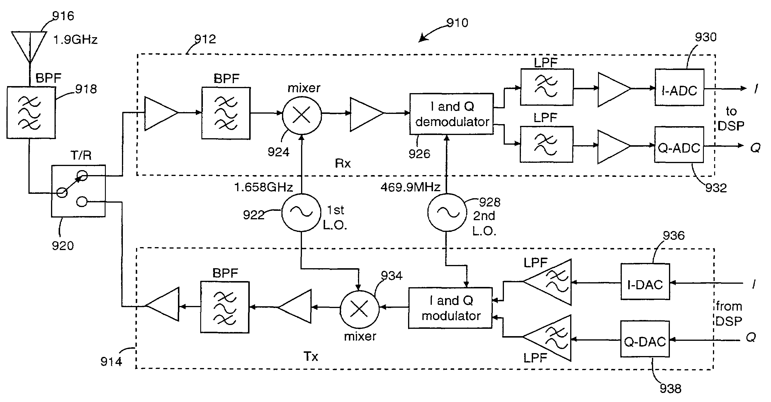
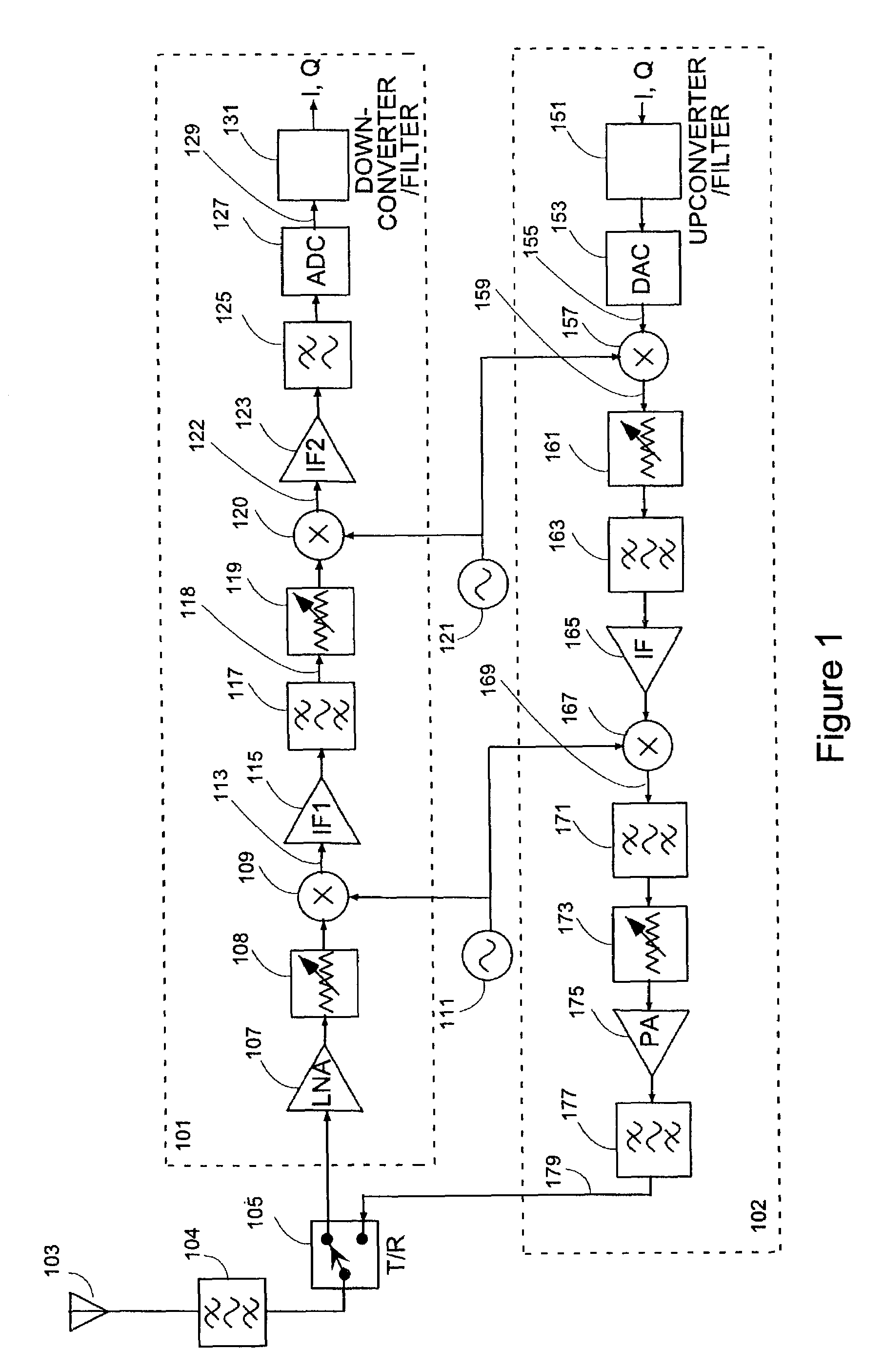
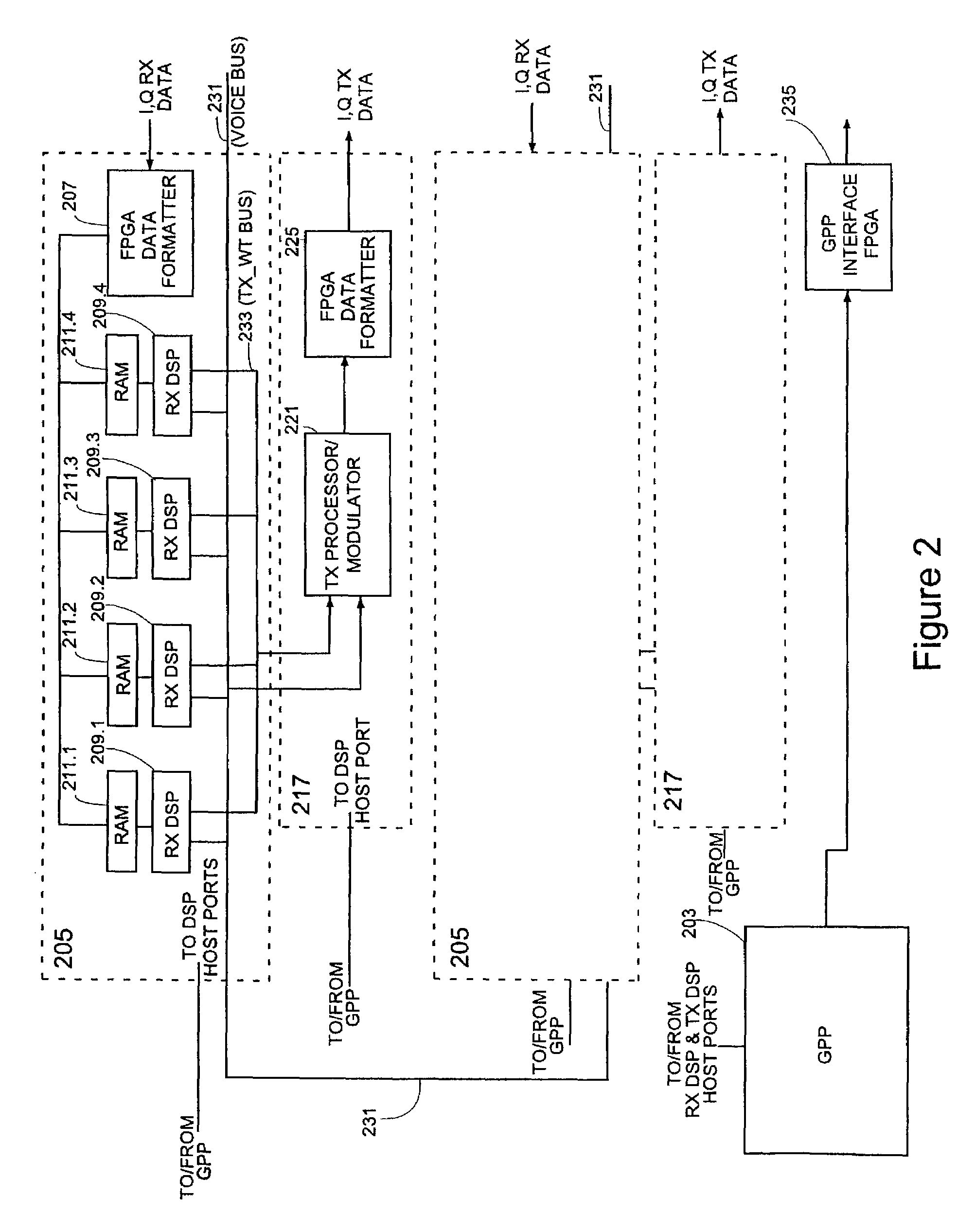
[0062]The methods of the invention may be implemented on any communication system which includes one or more communication stations and one or more remote receivers (for communication on the downlink) and transmitters (for communication on the uplink). The only requirement for the quality estimation aspects of the invention is that the modulation used includes some form of angle (e.g., phase) demodulation, and the only requirement for the downlink SDMA power control is the ability to determine downlink transmit weights, for example from received uplink signals. The methods of the invention preferably are implemented on a communication station which is a base station and on its subscriber units, which are part of a communication system in which a base station uses SDMA to communicate with its subscriber units. In the preferred embodiment, the communication system is meant for use in a wireless local loop (WLL) cellular system. While the subscriber units in the illu...


PUM


Abstract

A method for ongoing power control for a communication station with a multiple antenna array, the power control using a method for signal quality estimation applicable for angle modulated signals. One aspect of the ongoing power control method is applicable for the uplink and includes separating the joint determination of a receive weight vector and ongoing power control into a receive weight vector determining part and a separate transmit power adjustment part. In one embodiment, the ongoing power control method for the downlink includes separating the joint determination of a receive weight vector and ongoing power control into a receive weight vector determining part and a separate transmit power adjustment part. The method starts with one part, for example transmit power assignment. Receive weight vector determination is carried out with this assigned transmit power, and the new weights used. An estimate of the resulting received signal quality is obtained and used for new ongoing power adjustment. Another aspect is applicable for the downlink and includes one aspect of the ongoing power control method is applicable for the uplink and includes separating the determination of a complete transmit weight vector including the vector of relative transmit weights and the scaling to use with the relative transmit weights into a part for determining a set of relative transmit weights and a separate transmit power adjustment part that determines the scaling factor.

Description

CROSS-REFERENCE TO RELATED APPLICATION[0001]This application is a continuation application of U.S. patent application Ser. No. 09 / 020,049, entitled “Power Control with Signal Quality Estimation for Smart Antenna Communications Systems,” filed on Feb. 6, 1998 now U.S. Pat. No. 6,463,295 which, in turn, is a continuation-in-part of U.S. patent application Ser No. 08 / 729,387 filed Oct. 11, 1996 now U.S. Pat. No. 6,047,189, and entitled “An Adaptive Method for Channel Assignment in a Cellular Communication System,” hereinafter called the “Parent Patent.”FIELD OF INVENTION[0002]This invention relates to the field of wireless communication systems and more particularly to controlling radiated RF power level during establishment of a call and on an ongoing basis in a cellular wireless system, such control of power using an estimate of the quality of a received angle-modulated carrier.BACKGROUND OF THE INVENTION[0003]In a wireless communication system, as a general rule, it is highly desira...

Claims


Application Information

Patent Timeline
IPC IPC(8): H04B7/00
CPCH04B7/0848H04W52/42
Inventor YUN, LOUIS C.
Owner INTEL CORP
Learn More