
Expression miniarrays and uses thereof

Inactive Publication Date: 2006-04-25
GENETAG TECH
View PDF8 Cites 70 Cited by
  • Summary
  • Abstract
  • Description
  • Claims
  • Application Information

AI Technical Summary

Benefits of technology

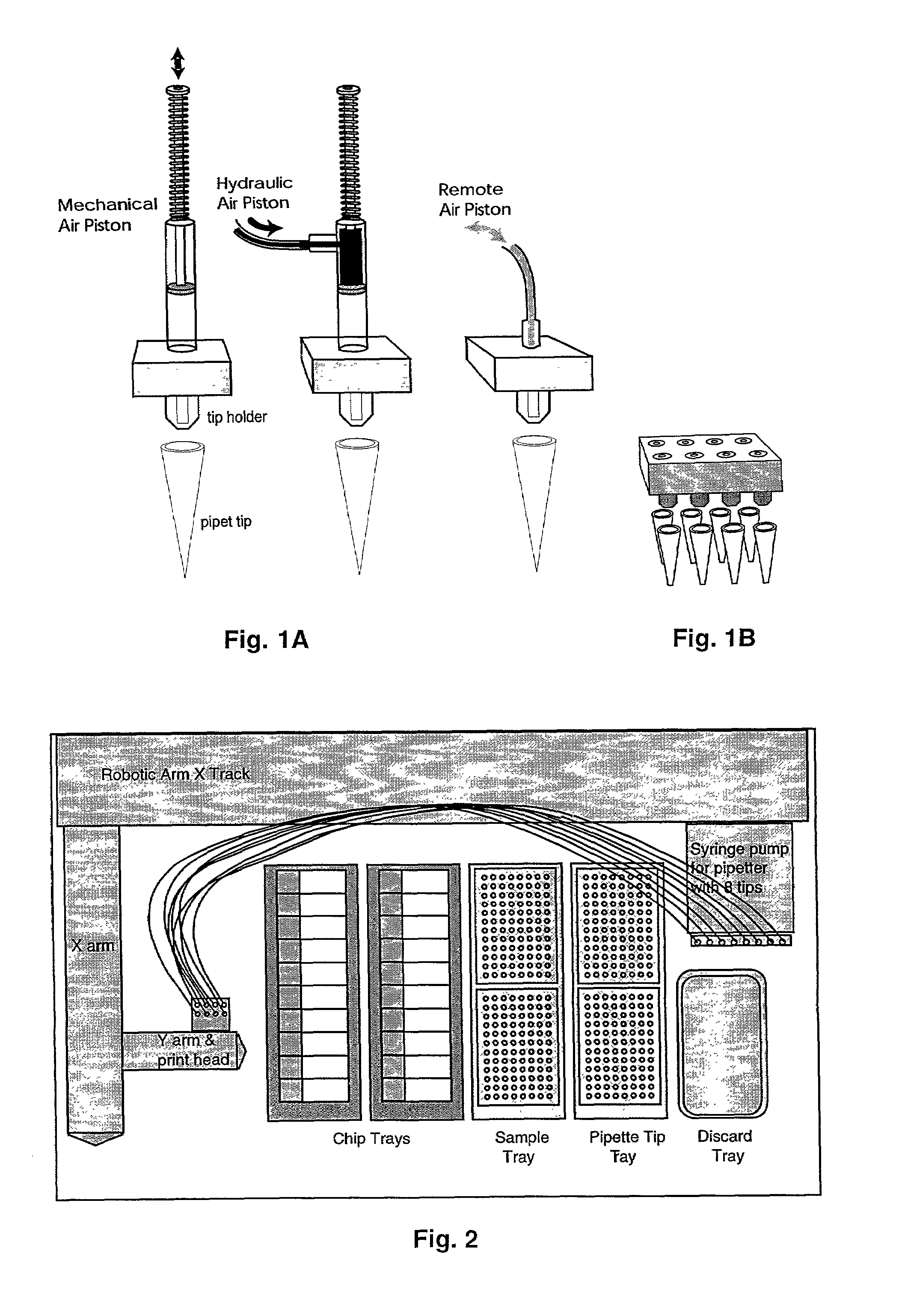
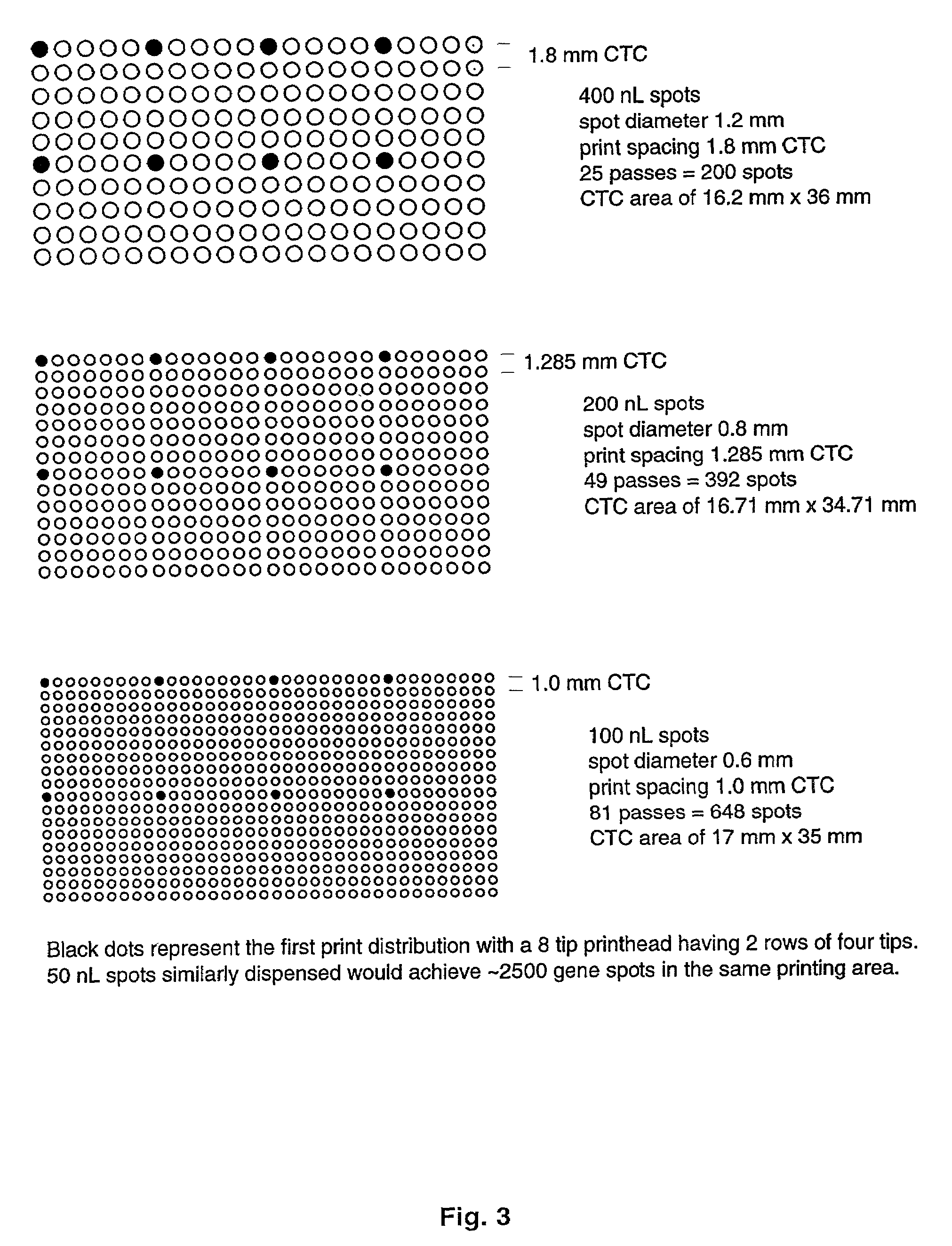
[0016]The present invention provides methods and devices for a new, inexpensive miniarray suitable for gene expression analysis. Mechanized large format miniarrays of low or high density was developed due to gains in sensitivity resulted from methods of signal amplification and probe amplification disclosed herein. In contrast to the making of very small, high-density expression microarrays which require: (1) very expensive spotters that deposit picoliter volumes per spot with delicate, miniaturized pins or inkjets; (2) special dust free and humidity conditions during manufacture, and (3) high resolution fluorescent image scanners for analysis, the present invention creates simpler, less expensive mini-format arrays based on employing automated pipetters which can reliably deposit nanoliter volumes of analyte specific reagents in a known grid pattern on solid or membrane supports.
[0017]The miniarray of the present invention is also designed to employ disposable pipette tips that can be ejected and replaced to avoid tip cleaning and contamination problems between loading of samples. The spotter apparatus of the present invention operates printing, loading, tip changing and other operations mechanically or robotically in order to facilitate miniarray manufacture. Fabrication of this miniarray is less sensitive to dust or humidity conditions, and arrays with larger spots can be analyzed with simpler, lower resolution scanners. The miniarray devices and methods disclosed herein are more refined than manually fabricated macroarrays, and the miniarrays provide economic, high quality expression assays that exhibit diagnostic value comparable or equivalent to the more expensive, high-density, microarray assays.

Problems solved by technology

Such macroarray formats are unsuitable for repetitive applications or high throughput, high-density analyses.
However, this approach remains largely a manual procedure with variation in spot size and volume, and limitations on reproducible manufacture.
These methods involved complex methods and equipment, and the probes generated were short (20 to 25 bases).
The need to miniaturize these expression arrays is due to the fact that mRNA samples available for such analyses are frequently quite limited and methods to amplify the sample products are inefficient.
Moreover, hybridization kinetics is very slow in large volumes of hybridization solution.
However, the development of these miniaturized, high density arrays comes at great cost and limitations, since the equipment required is complex and delicate, the pin heads or jets must be thoroughly washed and cleaned between sample loadings, specialized temperature and humidity controls and enclosures are required, and complex robotic procedures must be programmed for each run.
Such miniaturization also requires the use of very expensive, specialized labeling reagents.
Moreover, while these expression microarrays allow a high throughput overview and assessment of the relative frequency of different gene transcripts in a sample, these methods are limited by significant deficiencies in quantification and sensitivity (DeRisi et al., 1996; Duggan et al., 1999; Rajeevan et al., 1999).
However, effective multi-analyte amplification typically requires the provision of at least one unique primer for each type of gene product amplified, and commonly available PCR procedures such as RT-PCR and multiplex PCR have only been used successfully to amplify a limited number of the gene products in a sample (U.S. Pat. No. 5,807,680).
Inconsistency of these methods renders them useful only for identifying unusual or novel gene expression products, and they have not been devised or employed for use with expression microarrays or DNA chip analyses (Liang et al., 1993; Mou et al., 1994; Welsh et al., 1990; U.S. Pat. Nos. 5,262,311; 5,665,547; 5,580,726; 5,104,792; 5,789,206; 5,882,856).
The prime difficulty with many of these amplification methods stems from the use of short arbitrary or random primers mat can give variable results from gene to gene under different temperature and hybridization conditions such that they are unsuitable for repeated diagnostic analyses.
Therefore, some products may not amplify well, and rare or down-regulated transcripts may be under-represented (Khan et al., 1999).
Additionally, mammalian mRNA samples include very large gene transcripts 6 to 12 thousand nucleotides long that cannot be amplified reliably by routine PCR methods.
Consequently, global PCR amplification of a pool of mRNA-derived cDNA probes has not been attempted or successfully accomplished with DNA chip or expression microarray analyses.
Based on the above reasons, currently available exponential amplification methods cannot be validly applied to multi-analyte gene expression analysis.
However, such amplification is incremental and finite, with a typical duplication of 20–60 coples, and the amplified products it produces are antisense RNAs which are degradable (Philips at al., 1996; U.S. Pat. Nos. 5,972,607; 5,716,785).
However, this amplification method is also limited in the number of copies typically made from a sample (only 68 fold duplication demonstrated).
Thus, prior art regarding gene expression arrays is deficient in methods and instruments to amplify a test sample effectively, to create and analyze arrays easily and reliably, and to provide less costly arrays that possess equivalent or improved analytic and diagnostic value.

Method used


Image

  • Expression miniarrays and uses thereof
  • Expression miniarrays and uses thereof
  • Expression miniarrays and uses thereof

Examples


example 1

Miniarray Fabrication

[0070]Typically, electronic or mechanical controls activate the operations of the print head and enable it to be moved laterally and vertically in relation to the functional regions of the working platform. The loading of each pipette tip is achieved by a mechanical pump or piston that aspirates the liquid sample by vacuum, typically drawing 2 to 20 microliters per pipetter. Dispensing is controlled by first applying minute pressure on the piston to form a droplet of reagent on the pipette tip and secondly by touching said droplet to the surface of the miniarray substrate. Alternatively, the piston may be plunged sufficiently to pressure a droplet from the pipette tip until the droplet releases by gravity (see FIGS. 1). While air-based micropipetters are not effective in aspirating solution quantities of less than half a microliter, hand-controlled pipetters can be demonstrated to load microliter quantities and to dispense nanoliter quantities in the range of 20...

example 2

Diagnostic Miniarrays

[0078]The present invention also relates to methods wherein the miniarrays are designed on the basis of disease-specific gene expression patterns that are predicted from clinical information or prior expression studies. Prior art has demonstrated that two tissues can be compared by competitive two-color probe binding to the same microarray, wherein expression changes in the subject sample will produce distinct color shifts in individual gene spot depending on whether the activity of that gene is increased or decreased.

[0079]Exploiting these induced signaling differences, the diagnostic miniarrays of the present invention are structured to form visual patterns in the miniarray based on clustering together groups of gene spots that are either upregulated, downregulated or unchanged in the disease state as compared to normal tissue of the same origin. One such embodiment is to arrange such miniarrays for a particular disease in a stoplight pattern wherein the upreg...


PUM

PropertyMeasurementUnit
Lengthaaaaaaaaaa
Lengthaaaaaaaaaa
Lengthaaaaaaaaaa

Abstract

The present invention provides methods and devices for making new and inexpensive miniarrays suitable for gene expression analysis. Also provided herein are methods of diagnosis for specific tissue or condition using specialized diagnostic miniarrays that exhibit specific visual pattern as diagnostic readout.

Description

CROSS-REFERENCE TO RELATED APPLICATION[0001]This non-provisional patent application claims benefit of provisional patent application U.S. Ser. No. 60 / 248,247, filed Nov. 14, 2000, now abandoned.BACKGROUND OF THE INVENTION[0002]1. Field of the Invention[0003]The present invention relates generally to the field of gene expression array technology. More specifically, the present invention relates to the making and uses of larger format miniarrays that have similar analytic and diagnostic values as expression microarrays.[0004]2. Description of the Related Art[0005]Prior to the development of high density expression microarrays, low density nucleic acid hybridization arrays were commonly manufactured by hand or with limited automation. These low density nucleic acid hybridization arrays were used to detect concentration or sequence differences between samples or to simultaneously detect and compare complex analyte samples containing unknown products or a mix of multiple products. Geneti...

Claims


Application Information

Patent Timeline
IPC IPC(8): C12Q1/68B01J19/00B01L3/02C40B40/06C40B40/10C40B60/14G01N33/543G01N35/00G01N35/10
CPCB01J19/0046B01L3/0262B01L3/0268B82Y30/00G01N33/54386G01N35/1002G01N35/1065G01N2035/1034B01J2219/00369B01J2219/00385B01J2219/00527B01J2219/00585B01J2219/0059B01J2219/00596B01J2219/00605B01J2219/0061B01J2219/00612B01J2219/00626B01J2219/00637B01J2219/00659B01J2219/00677B01J2219/00689B01J2219/00691B01J2219/00702B01J2219/00722B01J2219/00725B01L3/0275B01L2400/02B01L2400/022B01L2400/027B01L2400/0487C40B40/06C40B40/10C40B60/14G01N35/1074G01N2035/00237G01N2035/103B01J2219/00317
Inventor SHAFER, DAVID A.
Owner GENETAG TECH
Learn More