Optical system and projection type image display apparatus equipped with optical system

a technology of optical system and image display apparatus, which is applied in the direction of lighting and heating apparatus, television system, instruments, etc., can solve the problems of reducing the realistic sensation, affecting the effect of presentation, so as to prevent the phenomenon of whitening and improve the video

Inactive Publication Date: 2006-04-25
MITSUBISHI ELECTRIC CORP
View PDF12 Cites 6 Cited by
  • Summary
  • Abstract
  • Description
  • Claims
  • Application Information

AI Technical Summary

Benefits of technology

[0014]An object of the present invention is to provide an optical system and a projection type image display apparatus capable of preventing the whitening phenomenon and improving video effects given to viewers as well as effectively utilizing light emitted from a light source for an image to be projected to display a projected image brightly.

Problems solved by technology

This causes a problem in that, although top and bottom regions of a image projection region on the screen where images are inherently unnecessary to be displayed need to be displayed in black, a part or the whole of the top and bottom regions is displayed brightly, that is, displayed in white (hereinafter referred to as a “whitening phenomenon”).
Such whitened region appears in the vicinity of a projected image, causing another problem in that, particularly in the application to a video projector and in viewing video in a dimly lit room in order to enhance a realistic sensation of video, such region interferes with viewing and reduces the realistic sensation.
Also, in the application to a data projector used for presentation or the like, viewers cannot concentrate on a projected image, causing the effect of presentation to be degraded.
Further, light outgoing from the light outgoing surface of the optical member is irradiated onto the whole area of the image display region of the reflection type display device, which means light incident upon a portion other than the central portion of the image display region is not utilized effectively.
This disadvantageously causes images projected onto the screen to be darkened.
Due to these factors, a conventional projection type image display apparatus cannot display images having an aspect ratio of 16:9 in good condition.

Method used


Image

  • Optical system and projection type image display apparatus equipped with optical system
  • Optical system and projection type image display apparatus equipped with optical system
  • Optical system and projection type image display apparatus equipped with optical system

Examples


first preferred embodiment

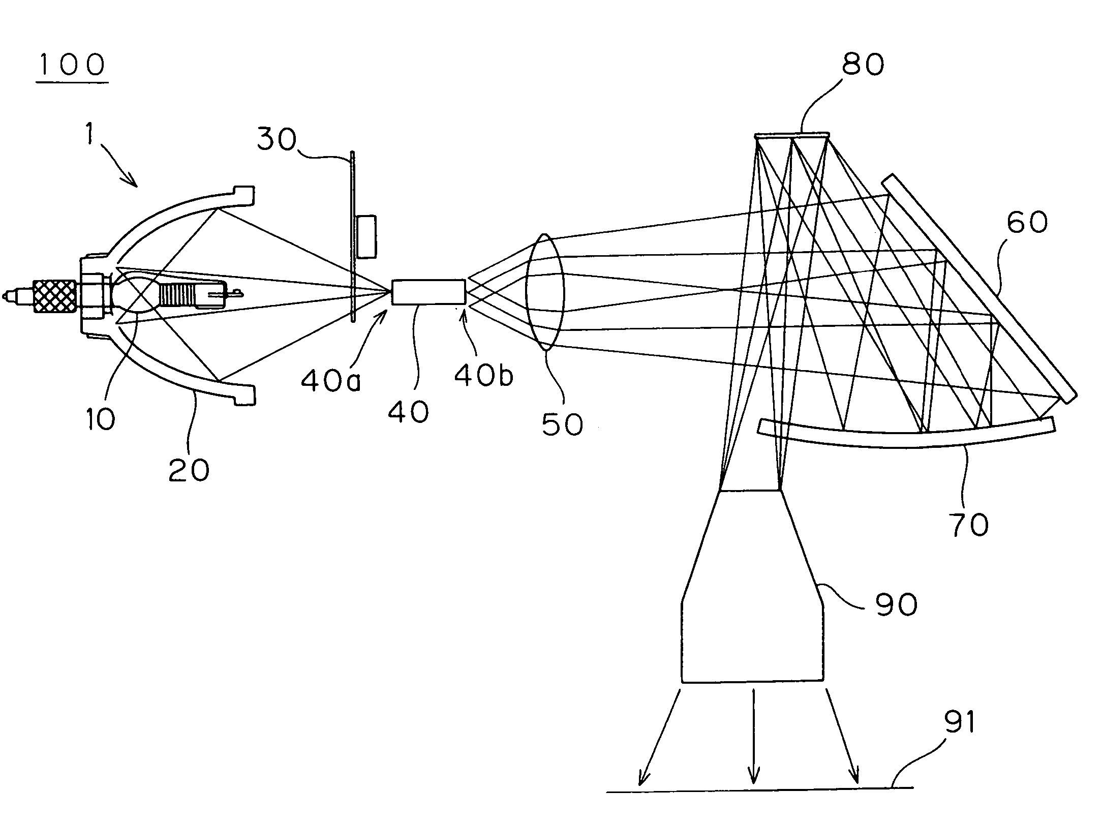
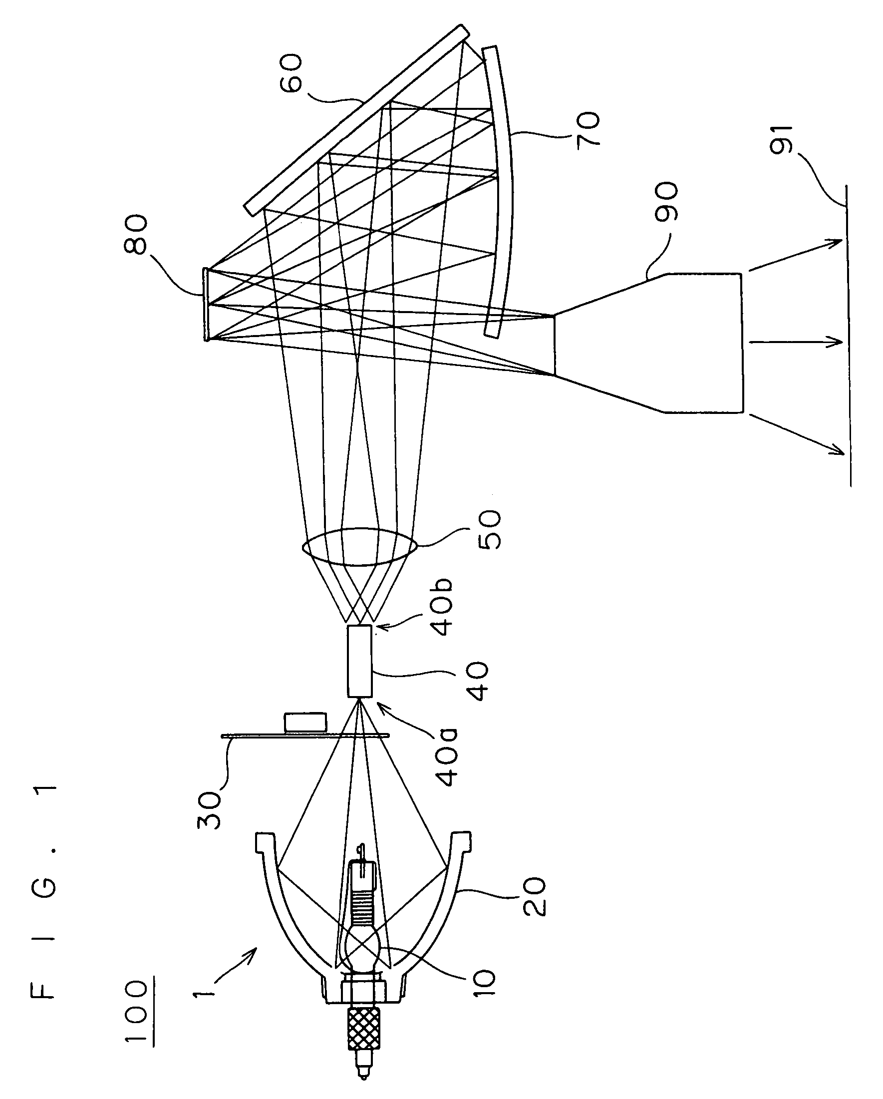
[0029]FIG. 1 illustrates the configuration of a projection type image display apparatus 100, and more particularly, an optical system 1 which is an essential part thereof. This optical system 1 is configured such that light emitted from a lamp source 10 follows an optical path passing through a lamp reflector 20, a color wheel 30, a light guiding member 40, a relay lens 50, a plane reflection mirror 60, a concave mirror 70, a reflection type display device 80 and a projection lens 90 to be projected onto a screen 91.

[0030]The lamp source 10 is a light source formed by a high pressure mercury lamp utilizing discharge or a halogen lamp, and light emitted from the lamp source 10 is reflected by the lamp reflector 20 provided to surround the lamp source 10. The lamp reflector 20 has a spheroidal surface that faces the lamp source 10 and is mirror-finished. The lamp source 10 is provided at one of the focal points of the spheroidal surface, and light emitted from the lamp source 10 is re...

second preferred embodiment

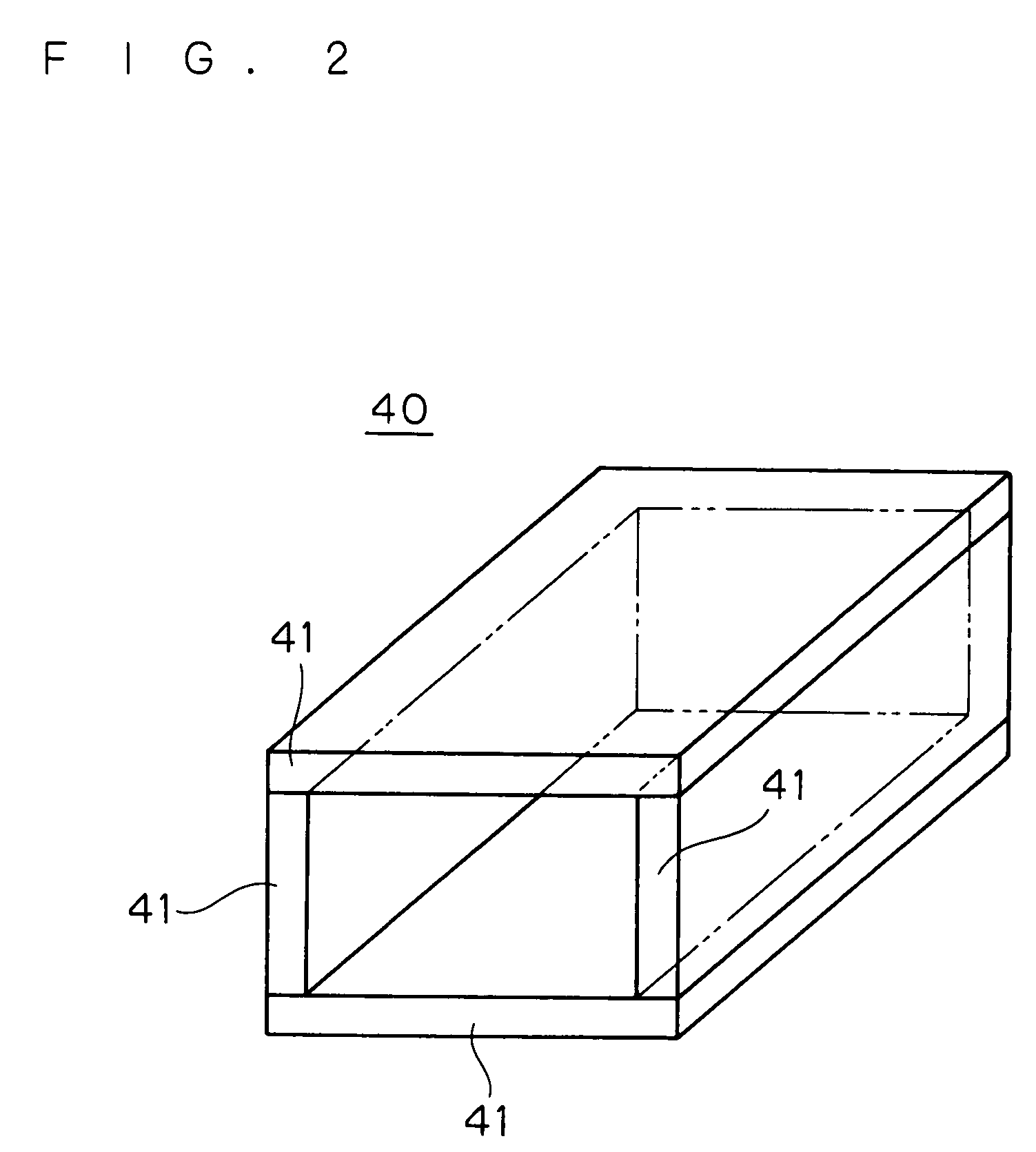
[0052]In a second preferred embodiment, description will be directed to an improvement in the case of using the light guiding member 40 as shown in FIG. 2. More specifically, an example of the light guiding member 40 configured as the so-called light pipe will be described in which light passing outside the mirror surfaces that face the hollow space for guiding light is interrupted. In the present embodiment, the overall configuration of the projection type image display apparatus 100 and optical system 1 is the same as that described above, repeated explanation of which is thus omitted here.

[0053]FIG. 8 illustrates the light guiding member 40 and a light shielding member 45 inserted into the optical path between the lamp source 10 and reflection type display device 80. The light guiding member 40 shown in FIG. 8 is the same as that described in the first preferred embodiment, and functions as a light pipe having a hollow space for guiding light formed by the plurality of glass memb...

third preferred embodiment

[0060]In a third preferred embodiment, description will be directed to an improvement of the above-described light shielding member. FIG. 9 illustrates the light guiding member 40 and a light shielding member 46 inserted into the optical path between the lamp source 10 and reflection type display device 80. The light guiding member 40 shown in FIG. 9 is the same as that described in the first preferred embodiment, and functions as a light pipe having a hollow space for guiding light formed by the plurality of glass members 41.

[0061]In the present embodiment, the light shielding member 46 is provided on the light outgoing side of the light guiding member 40 and on the end faces of the glass members 41. Such light shielding member 46 is formed by, for example, applying a light shielding coating or applying a light shielding tape on the end faces of the glass members 41.

[0062]Providing such light shielding member 46 on the end faces of the glass members 41 allows the unnecessary light ...


PUM


Abstract

A light guiding member (40) for reflecting therein light entering through a light entering surface (40a) several times to cause light having a uniform illumination distribution to outgo from a light outgoing surface (40b) is inserted into an optical path between a lamp source (10) and a reflection type display device (80). The light outgoing surface (40b) of the light guiding member (40) is formed in a dissimilar shape with an image display region of the reflection type display device (80), and a region irradiated with light in the image display region of the reflection type display device (80) is formed smaller than the image display region. This prevents a whitening phenomenon in a projected image undisplay region and improves video effects given to viewers as well as effectively utilizing light emitted from a light source for images to be projected to display projected images brightly.

Description

[0001]This nonprovisional application claims priority under 35 U.S.C. § 119(a) on Patent Application No. 2003-075394 filed in JAPAN on Mar. 19, 2003, the entire contents of which are hereby incorporated by reference.BACKGROUND OF THE INVENTION[0002]1. Field of the Invention[0003]The present invention relates to an optical system and a projection type image display apparatus configured to guide light emitted from a lamp source to an image display region of a reflection type display device along a predetermined optical path, to reflect a light component which forms an image to be projected by the image display region, and to project the reflected light component onto a predetermined screen.[0004]2. Description of the Background Art[0005]A conventional reflection type image display apparatus is known in which light emitted from a lamp source is guided to an image display region of a reflection type display device along a predetermined optical path, and a light component which forms an ...

Claims


Application Information

Patent Timeline
Patent Type & Authority Patents(United States)
IPC IPC(8): G03B21/28F21V7/00G02B6/00G03B21/14H04N5/74G02B27/18G03B21/00H04N9/31
CPCH04N5/74H04N9/3102H04N7/0122H04N5/7416
Inventor HORI, HIDEHIKO
Owner MITSUBISHI ELECTRIC CORP
Why Eureka
Try Eureka