Wheel chock restraint system
a technology of restraint system and chock, which is applied in the field of wheel chock restraint system, can solve the problems of not being designed to resist, trucks that cannot be secured by icc bars, hazardous loading and unloading operations, etc., and achieves the effects of convenient and effortless handling, convenient proper placement of chocks, and easy manipulation of chocks
- Summary
- Abstract
- Description
- Claims
- Application Information
AI Technical Summary
Benefits of technology
Problems solved by technology
Method used
Image
Examples
first embodiment
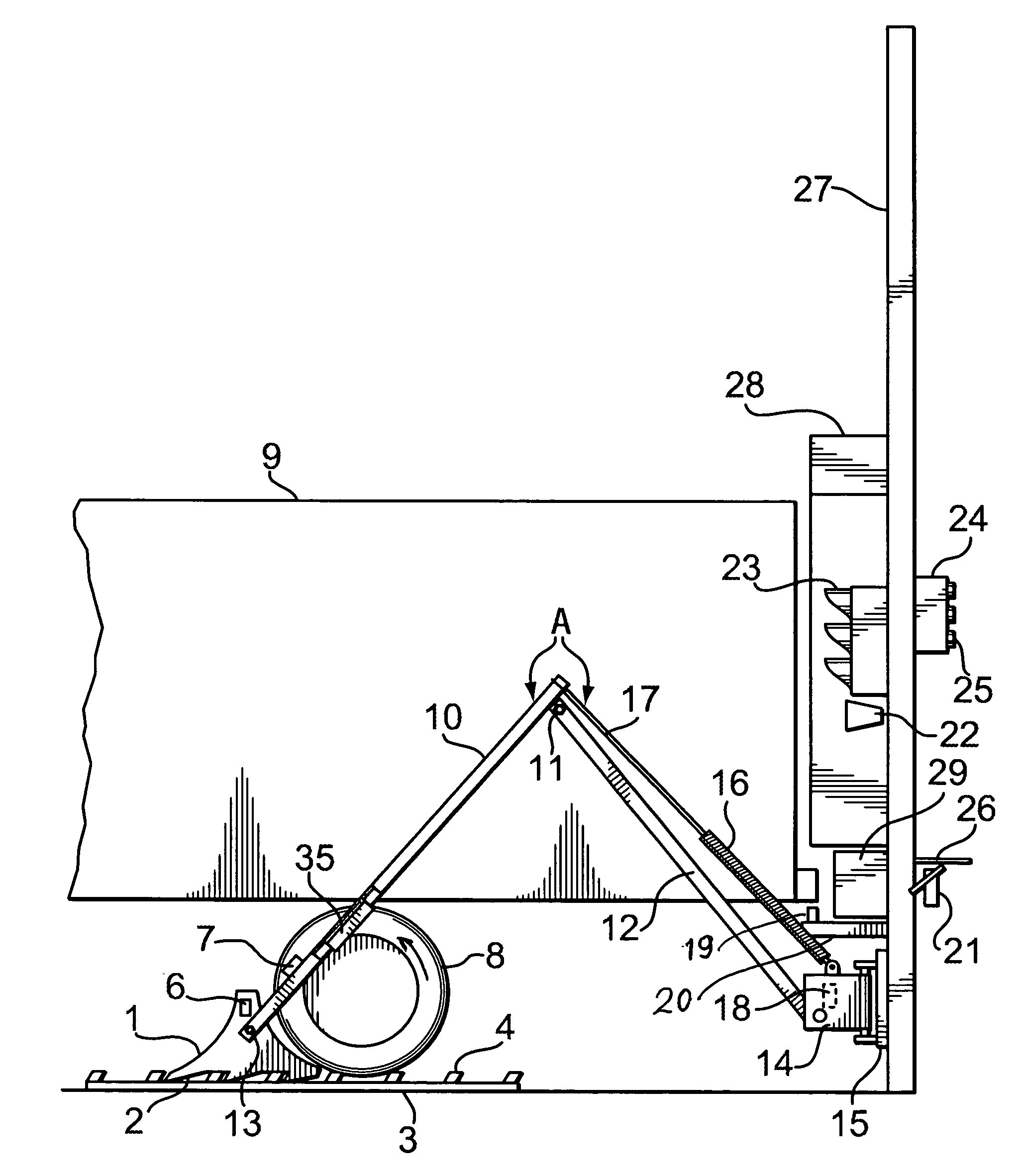
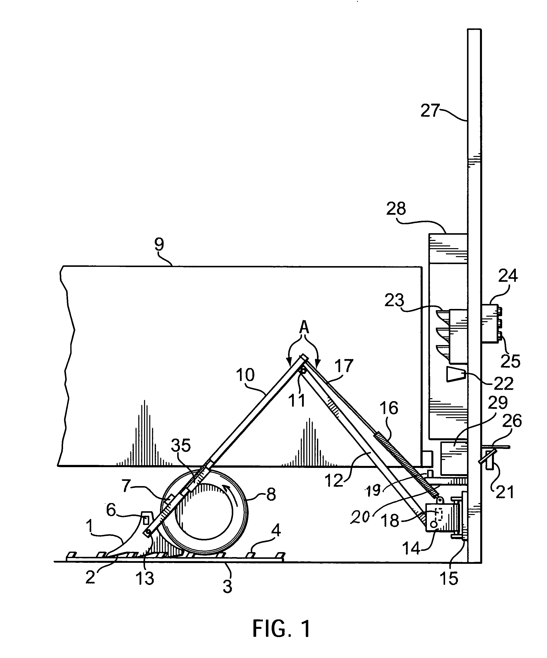
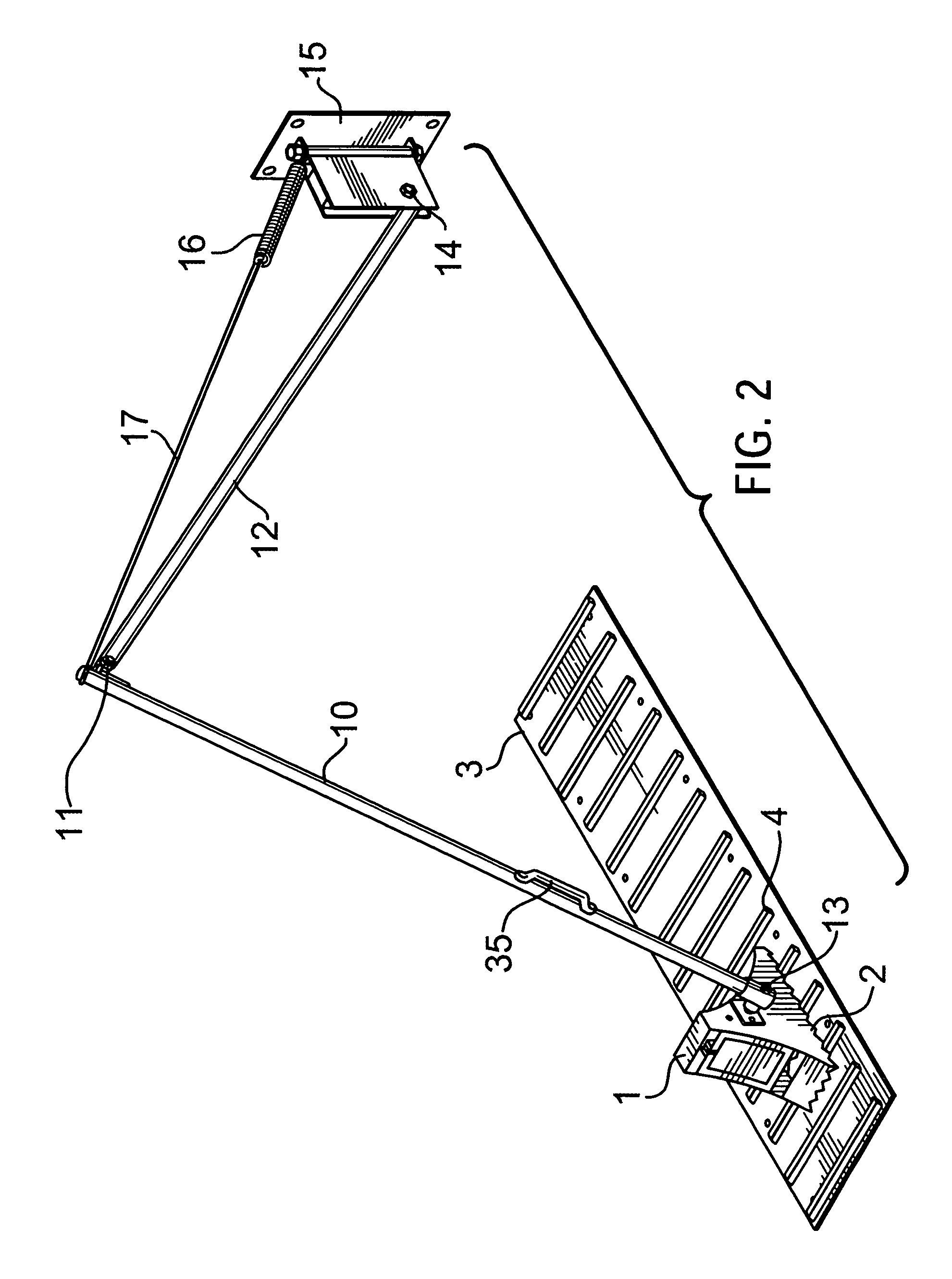
[0022]Referring to drawings, FIGS. 1 and 2 show the present invention comprising a wheel chock 1 attached to a wheel chock support means including a movable arm A consisting of a front arm 10 pivotally attached to a rear arm 12. Rear arm 12 is pivotally attached to a loading dock 27 by means of a pivot or bracket 14. A tension means such as an extension spring 16 is attached by one end to a pivot 14 and by another end to an upper portion of the front arm 10 by means of a cable or steel rod 17. Pivot 14 allows the arm A to be rotated left and right and up and down, and to move it into storage position, in close proximity to the dock face (not shown) when not in use.
[0023]A supporting element 3 is fixed on the ground in the vicinity of the loading dock and comprises an elongated plate long enough to spread at least under one axle of a truck 9 during loading operation to facilitate a proper engagement of a wheel chock 1 with the plate 3. A base portion of the chock 1 is provided with a...
second embodiment
[0033]FIG. 3 shows the present invention wherein instead of one spring there are used two springs 16a and 16b. In this embodiment spring 16b is attached between the pivot
[0034]For both embodiments shown on FIG. 1 and FIG. 3 the attachment point of cable or rod 17 depends upon the length of the front arm 10, weight of said arm 10 and chock 10 and the strength of the tension means.
[0035]FIGS. 4a, b and c show different modifications of the configuration of the base portion of the chock 1 and stoppers 4 of the supporting plate 3. FIG. 4a shows base portion of the chock provided with a plurality of angled teeth 2 extending doiwardly. Stoppers have configuration of a plurality of angled rods 4 extending upwardly from the plate 3 and inclined under an angle corresponding to the angle of the teeth 2. Stoppers 4a are mounted transversally along the plate 3. Such complimentary angled configuration of teeth 2 and stopper 4 allows a very secure engagement preventing the chock 1 from tumbling a...
third embodiment
[0048]FIG. 8 shows the present invention comprising the chock 1 and supporting plate 3 similar to the one shown on FIG. 1. In this embodiment, wheel chock support means comprise a handle 61 and set of wheels 62 mounted on a side of the chock 1. Chock 1 is moved to the proper position manually by the driver using handle 61 and wheels 62. There are also a set of skis 63 attached beside wheels 62 which may be used during winter season.
[0049]The present invention has the following advantages over all known systems:[0050]it is simple and easy to operate due to non-jamming mechanism of the arm;[0051]involves the driver in the safety process;[0052]interlocks with dock leveller;[0053]arm can be extended up to 14 feet from the loading dock;[0054]minimum maintenance is required;[0055]galvanized assembly provides excellent durability;[0056]non ICC bar dependent;[0057]easy snow removal when the alarm is stored;[0058]presence of highly visible warning system when truck departs prematurely;[0059]...
PUM
 Abstract
Description
Claims
Application Information
 - R&D
- Intellectual Property
- Life Sciences
- Materials
- Tech Scout
- Unparalleled Data Quality
- Higher Quality Content
- 60% Fewer Hallucinations
Browse by: Latest US Patents, China's latest patents, Technical Efficacy Thesaurus, Application Domain, Technology Topic, Popular Technical Reports.
© 2025 PatSnap. All rights reserved.Legal|Privacy policy|Modern Slavery Act Transparency Statement|Sitemap|About US| Contact US: help@patsnap.com


