Reciprocating saw comprising a program-controlled feed conveyor for advancing the item to be cut

a program-controlled feed conveyor and reciprocating saw technology, applied in the field of mill saws, can solve the problems of irregular saw blade stress, unfavorable etc., and achieve the effects of long service life of saw blades, high cutting rates, and favorable cutting conditions

Inactive Publication Date: 2006-04-25
WINTERSTEIGER
View PDF21 Cites 9 Cited by
  • Summary
  • Abstract
  • Description
  • Claims
  • Application Information

AI Technical Summary

Benefits of technology

[0008]Although basically each position of rotation of the slider-crank drive is suitable for timing the controlling system, a particularly favorable construction is achieved if the signal transmitter consists of a sensor for the dead center of the slider-rank drive at the end of the cutting stroke, as in this case the signal transmitter an be easily coordinated with the saw frame guide, without having to provide complex adjustment facilities. The dead center at the end of a cutting stroke makes it possible for the feed drive to begin operating already with the next cutting stroke in spite of the lead necessary for overcoming the saw blade disengagement.

Problems solved by technology

This circumstance entails irregular chips over the cutting stroke and thus irregular stresses of the saw blades with unfavorable consequences for the service life of the saw blades and for the cutting quality, in particular, when parquet lamellas are to be cut from commercially available stock lumber.
By intermittently reversing the control valve by the reversing shaft, however, irregular saw blade stress cannot be avoided.

Method used


Image

  • Reciprocating saw comprising a program-controlled feed conveyor for advancing the item to be cut
  • Reciprocating saw comprising a program-controlled feed conveyor for advancing the item to be cut
  • Reciprocating saw comprising a program-controlled feed conveyor for advancing the item to be cut

Examples


Embodiment Construction

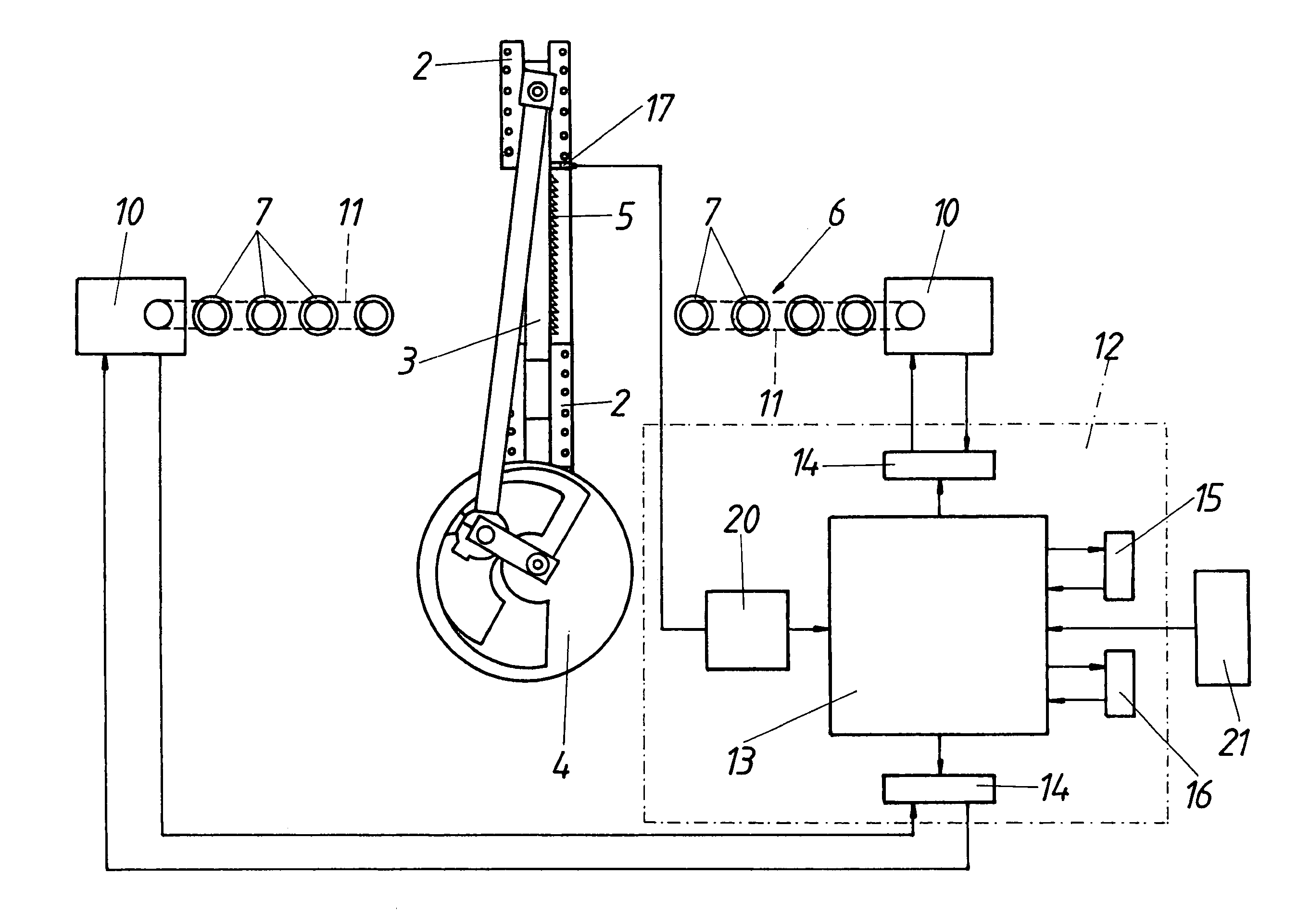
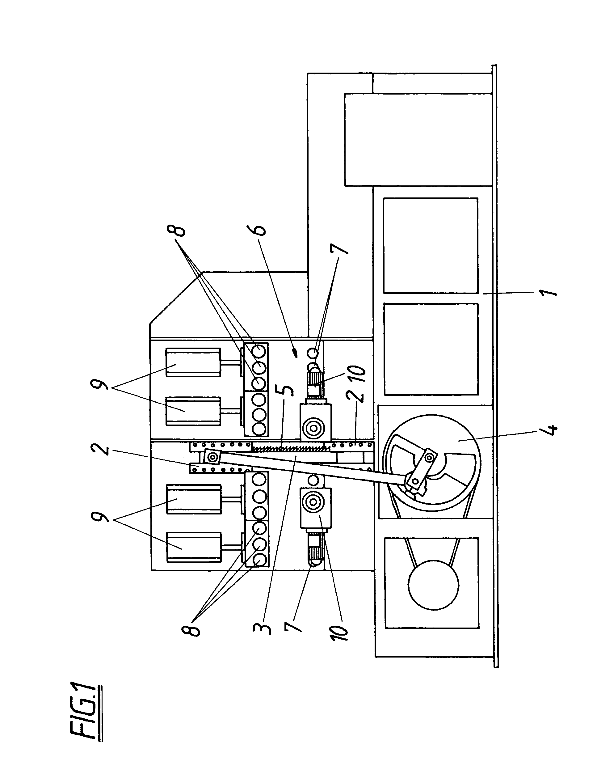
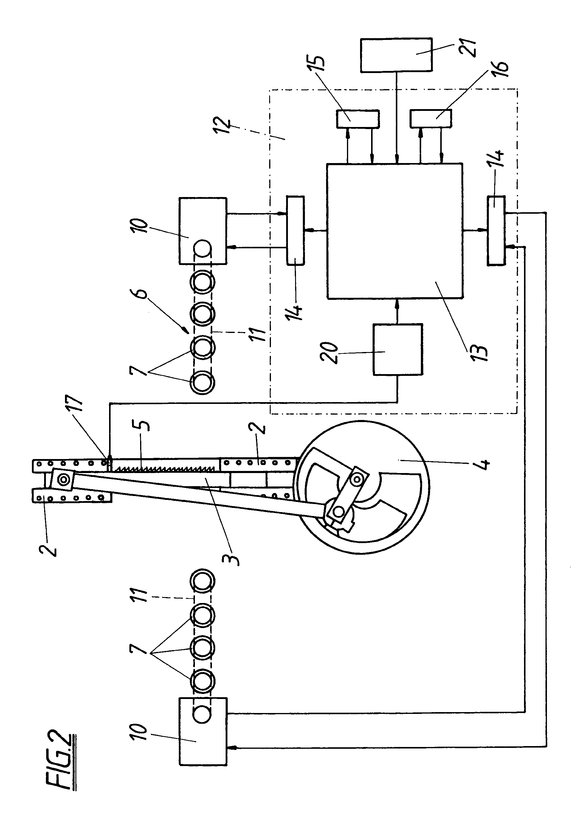
[0016]In the example of embodiment according to FIG. 1 the stand 1 of a mill saw is provided with a stroke guide 2 for a saw frame 3 that can be driven to and fro by means of a slider-crank drive 4. The parallel saw blades 5 of the saw frame 3 are gripped conventionally into a frame, which is adjustably cantilevered in the saw frame 3. For guiding the stock to be cut a feed conveyor 6 is provided, which consists of driven conveyor rolls 7 arranged upstream and downstream of the saw frame 3. The stock to be cut is against conveyor rolls 7 by pressure rolls 8, which can be set by adjustment cylinders 9. Contrary to conventional feed conveyors, the conveyor rolls 7 are not driven by the slider-crank drive 4, but by separate motors 10 connected thereto by chain drives 11, as shown in FIG. 2. These motors 10, designed as gear motors, are controlled by a controlling system 12, comprising a computer unit 13 according to FIG. 2 which transmit desired values to the position controllers 14 fo...


PUM

PropertyMeasurementUnit
frequencyaaaaaaaaaa
cutting speedaaaaaaaaaa
speedaaaaaaaaaa

Abstract

The description refers to a mill saw with a saw gate (3) driven via a slider-crank drive (4), whose parallel saw blades (5), which cut in only one stroke direction, are provided with a bias, and with a feed conveyor (6) for the stock to be cut, which is driven intermittently during the cutting stroke of the saw gate (3) as a function of the cutting speed by means of at least one motor (10) separated from the slider-crank drive (4) and connected to a controlling system (12). To achieve favorable construction features, it is suggested that the controlling system (12) connected to a signal transmitter (17) for a preset position of rotation of the slider-crank drive (4) controls the motor (10) in dependence on the response of the signal transmitter (17) according to a stored control program for one conveying step adaptable to the respective stroke frequency of the slider-crank drive (4).

Description

CROSS REFERENCE TO RELATED APPLICATIONS[0001]Applicants claim priority under 35 U.S.C. §119 of Austrian Application No. A333 / 99 filed on Mar. 1, 1999. Applicants also claim priority under 35 U.S.C. §365 of PCT / AT2000 / 00052 filed on Feb. 28, 2000. The international application under PCT article 21(2) was not published in English.FIELD OF THE INVENTION[0002]The invention relates to a mill saw with a saw frame driven by a slider-crank drive, whose parallel saw blades, which cut only in one stroke direction, are cantilevered, and with a feed conveyor for the stock to be cut, which is driven intermittently during the cutting stroke of the saw frame as a function of the cutting speed by means of at least one motor separated from the slider-crank drive and connected to a controlling system.DESCRIPTION OF THE PRIOR ART[0003]To ensure, in spite of the sinusoidal speed gradient, uniform chip thicknesses over the cutting stroke in case of mill saws with a saw frame driven by a slider-crank dri...

Claims


Application Information

Patent Timeline
Patent Type & Authority Patents(United States)
IPC IPC(8): B23D51/04B27B3/16B27B3/18B27B3/20
CPCB27B3/16B27B3/20B27B3/18Y10T83/4501Y10T83/4597Y10T83/6475Y10T83/6925
Inventor MAYR, REINHOLDDIERMAIER, FRANZ
Owner WINTERSTEIGER
Why Eureka
Try Eureka