
Suppression of perceived occlusion

a technology of perception and suppression, applied in the field of hearing aids, can solve the problems of acoustic feedback, occlusion effect electronic compensation, and discomfort of the position of the mechanical member in this part of the ear canal for the user, and achieve the effect of reducing the risk of occlusion

Inactive Publication Date: 2006-04-18
WIDEX AS
View PDF7 Cites 16 Cited by
  • Summary
  • Abstract
  • Description
  • Claims
  • Application Information

AI Technical Summary

Benefits of technology

[0008]It is a further object of the present invention to provide a fitting method leading to a suppression of a hearing aid user's perception of the occlusion effect.
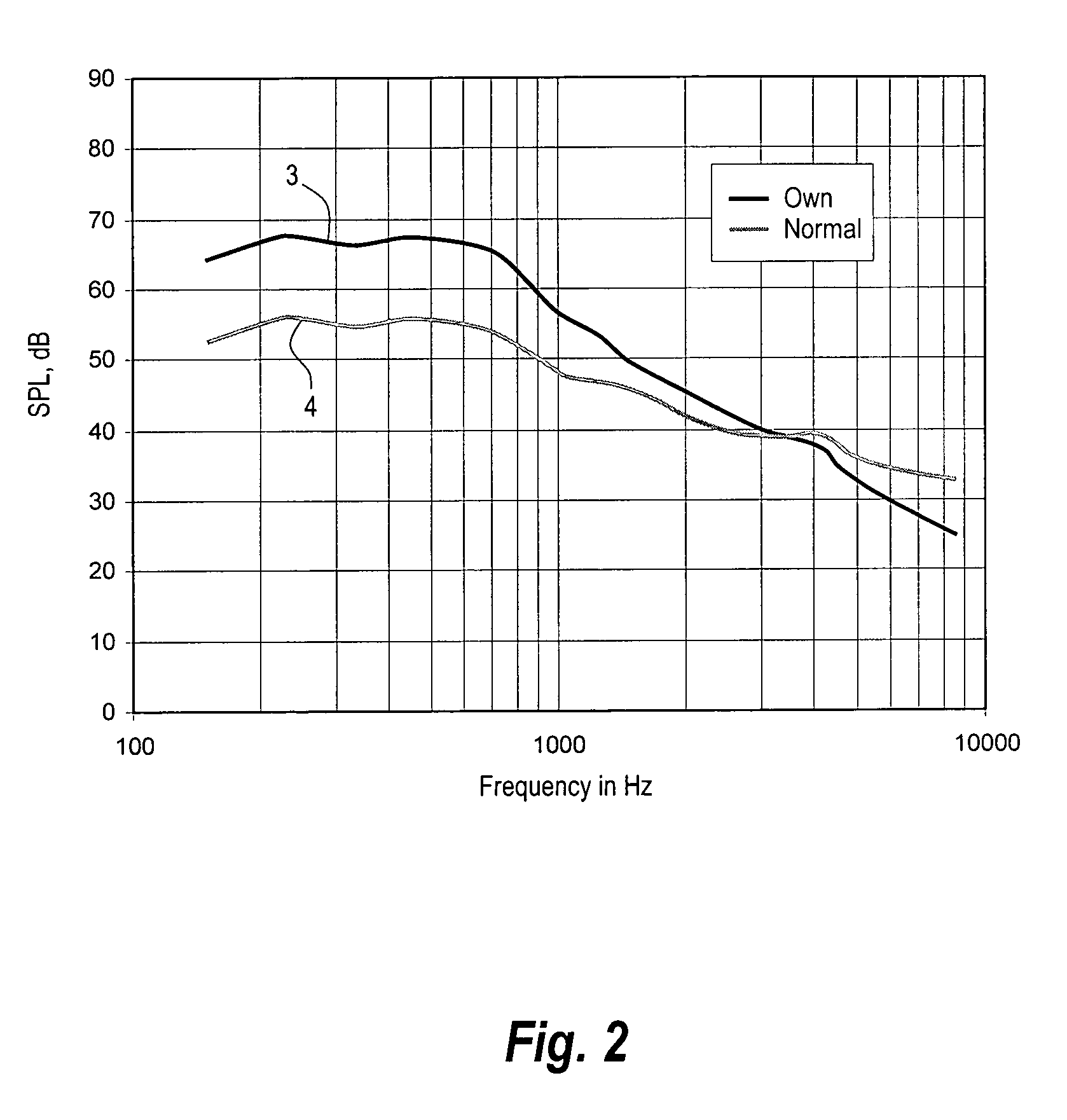
[0009]Research by the present inventors has shown that in some listening situations, hearing aid users perceive an improvement in sound quality when low frequency bands are enhanced, i.e. the above-mentioned “barrel perception” becomes less noticeable. However, in some other listening situations, e.g. during conversation, the hearing aid user perceives an improvement in sound quality when low frequency bands are attenuated, probably because of amplification of bone conducted speech.
[0010]The present invention exploits the fact that the eardrum of a user receives the user's own speech from two different propagation paths. In addition to the bone conducted speech mentioned above, sound waves also propagate through air from the mouth and around the head to the ear where it is received by the hearing aid. Also for air conducted speech, low frequencies are enhanced since the head attenuates high frequencies leaving low frequencies unaffected.
[0013]Further, in listening situations, low signal frequencies are enhanced whereby suppression of the occlusion effect in listening situations is obtained.

Problems solved by technology

However, the bony part of the ear canal is typically very sensitive and positioning of a mechanical member in this part of the ear canal may be uncomfortable to the user.
However, the vent may cause acoustic feedback.
Amplification of the received signal may lead to generation of a stronger acoustic output signal and eventually the hearing aid may oscillate.

Method used


Image

  • Suppression of perceived occlusion
  • Suppression of perceived occlusion
  • Suppression of perceived occlusion

Examples


Embodiment Construction

[0028]FIG. 3 shows a plot of a prior art compressor characteristic, i.e. a plot of the compressor output level as a function of the input level, both in SPL. The characteristic comprises two linear segments 5, 6, that are interconnected at a knee-point 10, typically positioned at 50 dB SPL input level. Below the knee point 10, the linear segment 7 has substantially no compression, i.e. the gain is a constant gain, suitable for compensating the hearing loss at low input signal levels. Above the knee point 10, the segment 6 has a compression ratio above 1, typically 2:1, for compensating for recruitment. Recruitment denotes the effect of a sensorineural hearing loss where loudness increases rapidly with increased sound pressure just above the hearing threshold and increases normally at high sound pressures. The hearing threshold is the lowest sound level at which sound is perceived. The compression ratio of a segment is equal to the reciprocal value of the slope of the segment. In a l...


PUM


Abstract

A fitting method is provided for a multichannel hearing aid with at least one low frequency channel having an individually adjustable compressor. The method comprises the steps of first adjusting the characteristic of the compressor according to the hearing loss to be compensated by the hearing aid, followed by the step of increasing the compression ratio of the characteristic of the compressor in the at least one low frequency band. The at least one low frequency channel may further comprise an offset amplifier adding an offset gain to the compressor characteristic, and the method may further comprise the step of adjusting the offset gain in the range from −20 dB to 20 dB. After adjustment according to the method, compressors operating at low frequencies enhance low level signals and attenuate high level signals whereby perception of occlusion is suppressed.

Description

FIELD OF THE INVENTION[0001]The present invention relates to a hearing aid with means for suppression of perceived occlusion.BACKGROUND OF THE INVENTION[0002]The occlusion effect denotes the low frequency enhancement in the loudness level of bone conducted signals due to occlusion of the ear canal. Some users having an earmold or a hearing aid in the ear canal blocking the canal complain that they have a perception of being in a barrel. In particular, their own voice sounds as if they speak in a barrel.[0003]FIG. 1 shows plots of sound pressure level (SPL) in the ear canal as a function of frequency for a sound with a specific frequency spectrum. SPL is the quantity of sound energy relative to a reference pressure: 20 μPa. The plotted SPL is measured in two situations. Curve 1 shows SPL measured in the occluded ear canal, and curve 2 shows SPL measured in the non-occluded ear canal. It is shown that for low frequencies, the SPL is approximately 10–30 dB higher for an occluded ear ca...

Claims


Application Information

Patent Timeline
IPC IPC(8): H04R25/00
CPCH04R25/70H04R25/505H04R2460/05
Inventor LUDVIGSEN, CARL
Owner WIDEX AS
Learn More