
Neutral control for vehicular automatic transmission

Inactive Publication Date: 2006-04-18
TOYOTA JIDOSHA KK
View PDF12 Cites 13 Cited by
  • Summary
  • Abstract
  • Description
  • Claims
  • Application Information

AI Technical Summary

Benefits of technology

[0007]In view of the foregoing problems, it is an object of this invention to improve the durability of a friction apply device while maintaining an improvement in fuel efficiency achieved by a neutral control.
[0009]In this kind of automatic shift system, a plurality of engaging elements are applied to achieve a running speed. When the neutral control is executed, the controller can switch the engaging element to be released or made to slip from one of the engaging elements to another of the engaging elements. As a result, it is possible to continue to execute the neutral control without the durability of the friction apply device being impaired by heat load, for example, thereby increasing the fuel efficiency effect and the like achieved by the neutral control.
[0012]Accordingly, prohibiting the neutral control when both of the heat loads of the plurality of friction apply devices are high makes it possible to prevent the durability of the friction apply device from being impaired by the heat load generated during the neutral control.
[0014]According to this structure, the neutral control can be executed not only in the first speed, which has the largest gear ratio, but also in forwards speeds of a second speed, which has the second largest gear ratio, and higher, even when the vehicle is running. As a result, it is possible to achieve an even greater fuel efficiency effect and the like by the neutral control than can be achieved when neutral control is only executed while the vehicle is stopped or in the first speed.
[0018]The neutral control that interrupts the transmission of power essentially serves to increase energy efficiency, such as fuel efficiency, by reducing the load on the source of driving force such as the engine. Accordingly, it is desirable that the engaging element be completely released, but the transmission of some power as the engaging element slips is permissible. Execution of the neutral control when the vehicle is stopped also inhibits the generation of creep torque.
[0019]The controller is adapted to fundamentally select a predetermined one, for example, from among the plurality of engaging elements, to be used in the neutral control. If the selected engaging element is unusable for some reason, e.g., if its heat load is high, or if its use is inappropriate, the controller selects another engaging element to be used. It is also possible, however, to mechanically switch between engaging elements alternately or sequentially every predetermined number executions, or at predetermined intervals of execution, of the neutral control, for example. When the neutral control is executed in a plurality of forward speeds, selecting a common engaging element that is to be applied throughout the plurality of forward speeds enables continued execution of the neutral control while downshifting when, for example, the vehicle speed drops as a result of the accelerator being off, by releasing or applying other engaging elements.

Problems solved by technology

When the hydraulic fluid temperature is so high that the volumetric efficiency of the pump is reduced, however, the apparatus cancels the neutral control to facilitate responsiveness during torque restoration.
This kind of slip control, however, generates a heat load on the friction apply device.
If great enough or sustained long enough, the heat load may impair the durability of the friction apply device.
Although it is possible to improve the durability of the friction apply device by, for example, increasing the number of friction plates lined with friction material, increasing the heat-resistance of the friction material, or increasing the amount of hydraulic fluid supplied for cooling, implementing these measures would either make the apparatus complex or increase costs, neither of which is desirable.
This would negate the improvement in fuel efficiency improvement that the apparatus was designed to achieve.

Method used


Image

  • Neutral control for vehicular automatic transmission
  • Neutral control for vehicular automatic transmission
  • Neutral control for vehicular automatic transmission

Examples


Embodiment Construction

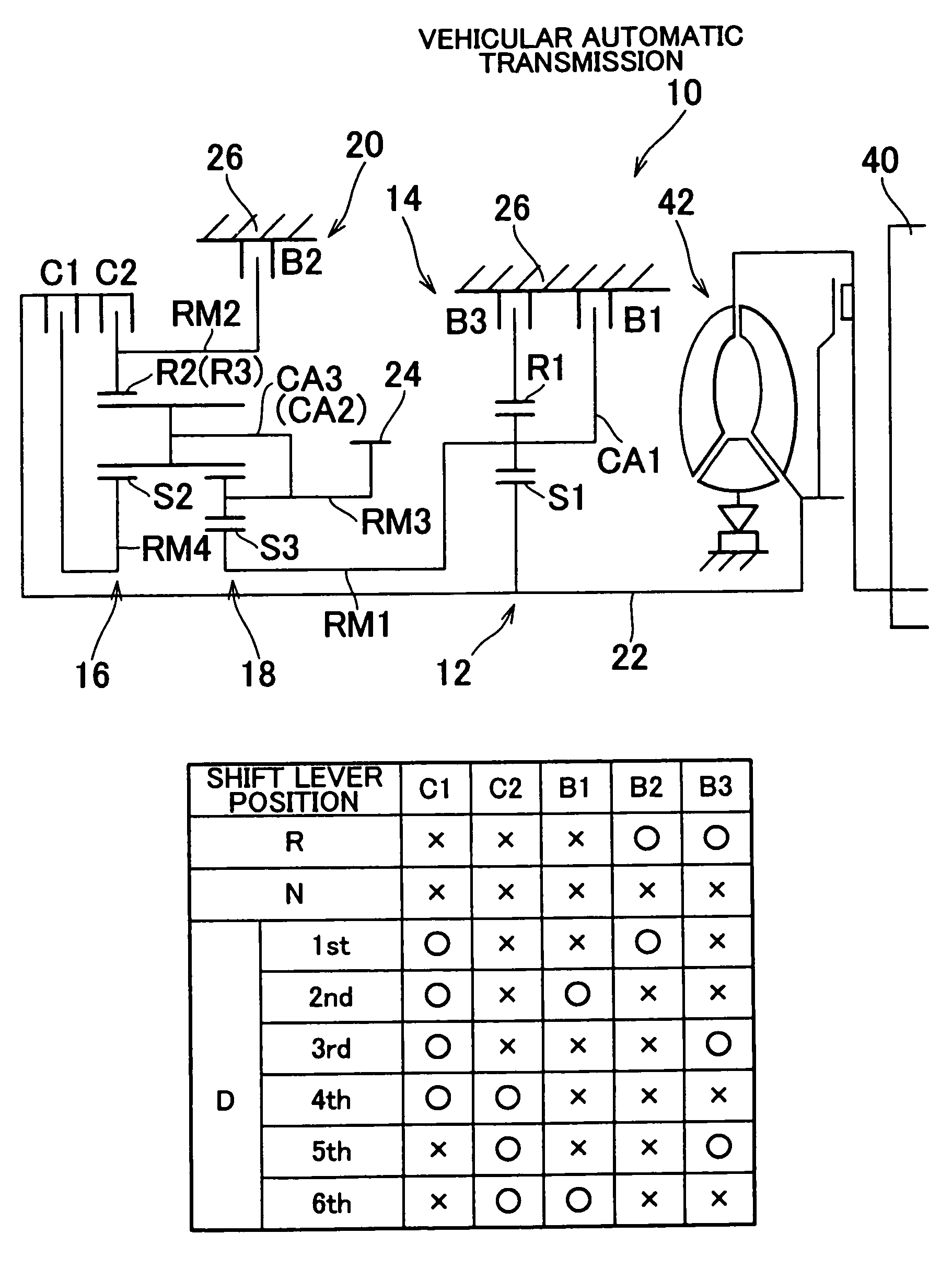
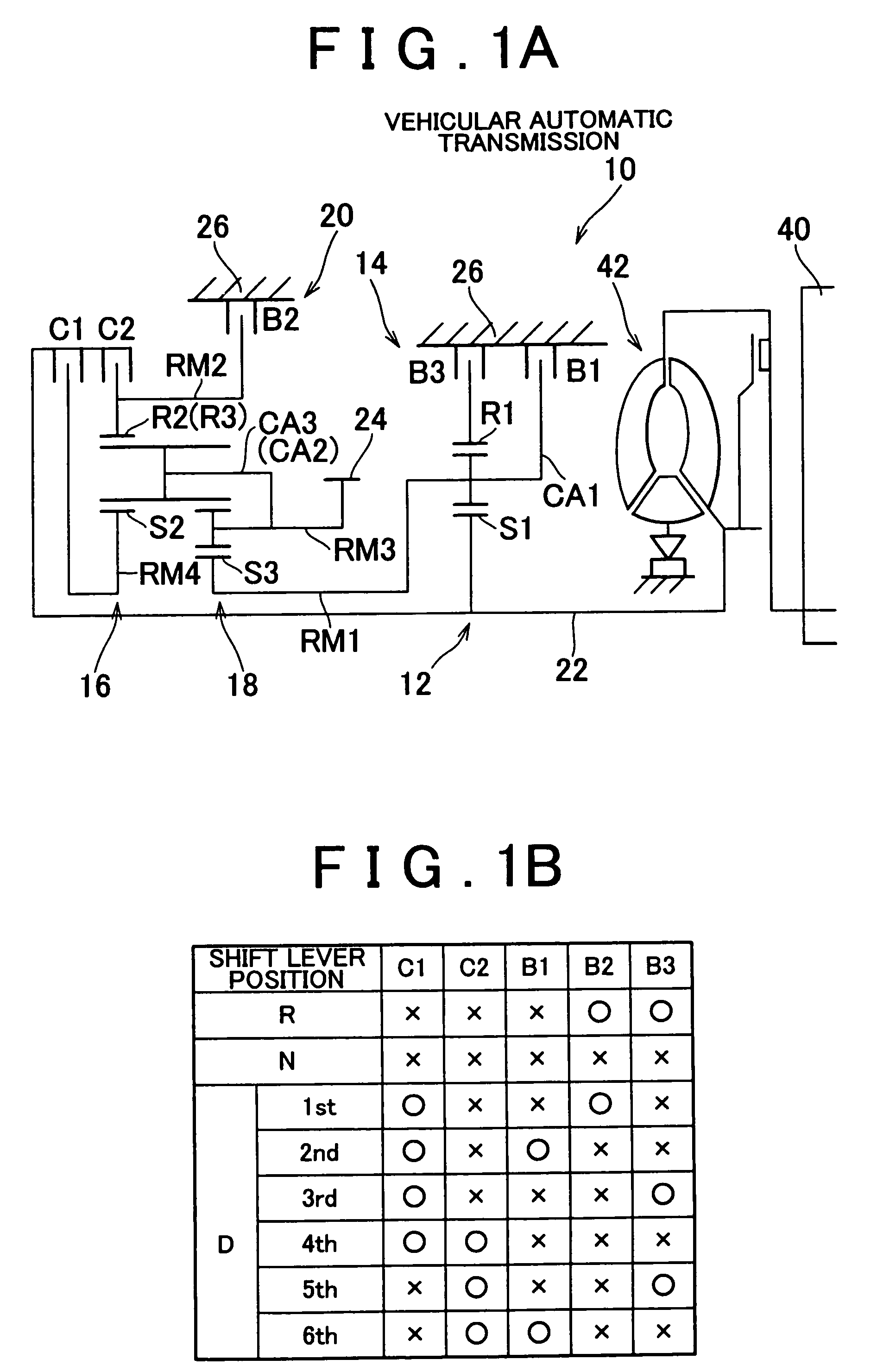
[0027]In the following description and the accompanying drawings, the present invention will be described in more detail in terms of exemplary embodiments. FIG. 1A is a skeleton view of a vehicular automatic transmission 10 to which the invention can be applied, and FIG. 1B is a clutch and brake application chart showing various application and release combinations of clutches and brakes to achieve specific speeds in the automatic transmission 10 shown in FIG 1A. The automatic transmission 10 is a transverse-mounted transmission for use in, for example, a FF (front engine, front drive) vehicle. This automatic transmission 10 includes a first transmitting portion 14 and a second transmitting portion 20 aligned on the same axis. The main component of the first transmitting portion 14 is a single pinion type first planetary gear set 12. The main components of the second transmitting portion 20 are a single pinion type second planetary gear set 16 and a double pinion type third planetar...


PUM


Abstract

A friction apply device, from among each pair of friction apply devices that are applied to achieve a speed from first speed to fourth speed, that is to be placed in a slipping state is selected based on a heat load when a neutral control is executed. As a result, it is possible to continue to execute the neutral control without the durability of the friction apply device being impaired by the heat load, for example, thereby increasing a fuel efficiency effect and the like achieved by the neutral control.

Description

INCORPORATION BY REFERENCE[0001]The disclosure of Japanese Patent Application No. 2003-151479 filed on May 28, 2003, including the specification, drawings and abstract is incorporated herein by reference in its entirety.BACKGROUND OF THE INVENTION[0002]1. Field of the Invention[0003]The invention relates to a vehicular automatic transmission. More specifically, the invention relates to an improvement in a neutral control that interrupts the transmission of power when driving while an automatic transmission is in a running speed.[0004]2. Description of the Related Art[0005]A known neutral control apparatus for a vehicular automatic transmission includes (a) an automatic transmission in which a shift is achieved by the application of a predetermined engaging element, and (b) neutral control executing means for executing a neutral control that interrupts the transmission of power by either releasing the engaging element, or allowing it to slip, when a predetermined condition to execute...

Claims


Application Information

Patent Timeline
IPC IPC(8): F16H31/00F16H61/20F16H61/686F16H61/02
CPCF16H61/20F16H2059/725F16H2061/202F16H2200/2007F16H2200/2023F16H2200/0052
Inventor SUGAWARA, AKIOMORISE, MASARUMIYATA, HIDEKIYASUDA, YUJITAKEUCHI, HIROAKI
Owner TOYOTA JIDOSHA KK
Learn More