
Multirate spectral analyzer with adjustable time-frequency resolution

a multi-band, time-frequency resolution technology, applied in the field of nonparametric spectral analysis, can solve the problems of failure to cancel aliasing, inability to eliminate aliasing, and inability to consider multi-band structures for general purpose spectrum analyzers, so as to reduce the effect of aliasing in the frequency domain and greater flexibility in the selection of temporal overlap

Active Publication Date: 2006-04-11
MITRE SPORTS INT LTD
View PDF28 Cites 18 Cited by
  • Summary
  • Abstract
  • Description
  • Claims
  • Application Information

AI Technical Summary

Benefits of technology

[0013]The present invention implements a high order prototype filter from which polyphase bandpass filters are derived to mitigate the effects of aliasing in the frequency domain. Additionally, the present invention allows greater flexibility in the selection of temporal overlap in the computation of the spectral estimates.

Problems solved by technology

Despite its popularity in coding applications, multirate subband structures have not been considered for use as general purpose spectrum analyzers.
However, in spectral analysis, unlike in coding, no decoding is performed so aliasing cannot be eliminated.
Because multirate subband structures have rarely been considered outside the context of perfect reconstruction coding, failure to cancel aliasing has been the primary obstacle in such structures being utilized in general purpose spectral analysis.
Furthermore, the redundancy removal and psychophysical advantages mentioned for coding systems are not relevant to stand-alone spectrum analyzers.
Thus, as most of the advantages mentioned previously no longer hold, the utility of multirate subband structures as stand-alone spectrum analyzers has not been widely recognized.
However, the spectrum analyzer of Tkacenko and Vaidyanathan utilizes a staionary, parametric model and, thus, its use in general purpose spectral analysis is extremely limited.
However, as the design of the disclosed filter bank is set by goals of hardware efficiency, effects of aliasing on the signal are overlooked.
The effects of aliasing decreases the signal-to-noise ratio, which is especially problematic near the passband edges, as disclosed in the Specification of the reference.
Thus, relief from aliasing in this manner may not be acceptable in certain applications, including that described in U.S. Pat. No. 6,085,077, which requires an instantaneous measurement.
In many applications, this limitation reduces the ability for system optimization by, for example, requiring additional time to obtain spectra that may have more overlap than required or decreasing the accuracy in the spectral estimate by not having enough overlap in the temporal data stream.

Method used


Image

  • Multirate spectral analyzer with adjustable time-frequency resolution
  • Multirate spectral analyzer with adjustable time-frequency resolution
  • Multirate spectral analyzer with adjustable time-frequency resolution

Examples


Embodiment Construction

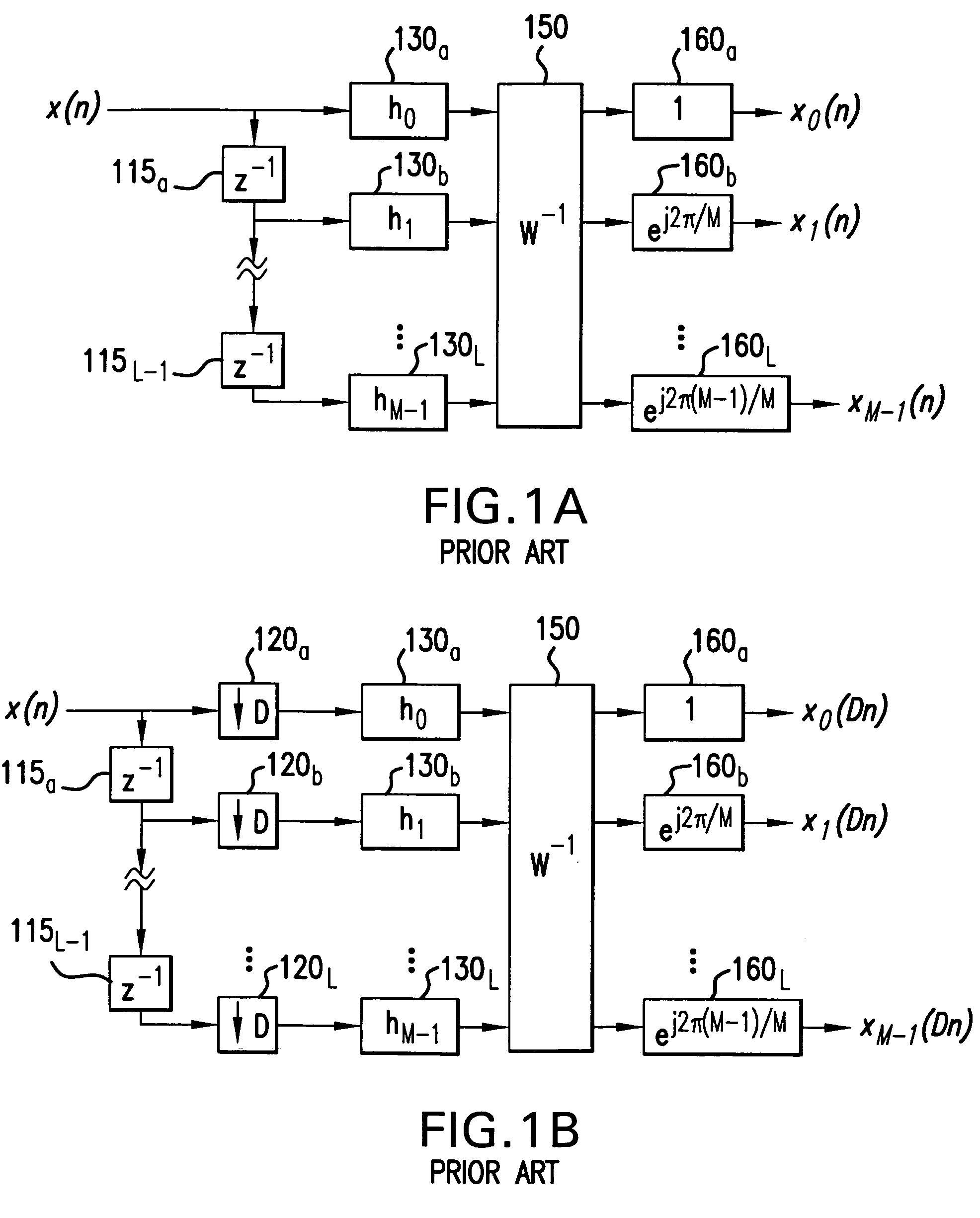
[0033]FIG. 1A illustrates a uniform DFT filter bank as is known in the art. The DFT filter bank is composed of a tapped delay line formed of delay elements 115a–115L-1, multipliers 130a–130L, transform processor 150 and phase compensators 160a–160L. The matrix W in transform processor 150 is the DFT matrix, W(m,k)=WMmk, and where WM=e−j(2π / M) and 0≦m,k≦M−1. The entire structure is exactly equivalent to a conventional, M-point, block-oriented DFT with an overlap of M−1 samples. Note that an inverse DFT matrix, W−1, as well as additional phase factors ej(2πk / M) are required because the delay chain, in effect, reverses the order of the input samples.

[0034]The transfer function of the baseband FIR filter is defined as:

[0035]H0⁢⁢(z)=∑k=0N⁢⁢hk⁢⁢z-k=∑k=0M-1⁢⁢hk⁢⁢z-k.(1)

For the DFT, the baseband filter order N=M−1 by definition as indicated in Eq. (1). It will be assumed that:

h(k)=hLP(k)w(k), k=0, 1, . . . , N,  (2)

and that a normalization is performed so that Σn=0Nhk=1. The window function...


PUM


Abstract

A multirate spectral analyzer receives a data sequence through a tapped delay line (510) onto a plurality of filter channels, each of which includes a first decimator (520), a polyphase filter (530), and a second decimator (540). Each filter channel is coupled to a transform processor (550) which modulates the frequency response of the polyphase filters to a plurality of identical bandpass filters spaced evenly at 2πk / M intervals, where k=1, 2, . . . , M−1, and M is the number of filter channels. The transform processor (550) outputs a plurality of time series representative of the frequency component for each of the corresponding filter channels. By choosing a prototype filter order to be much larger than the number of filter channels, the effects of aliasing in the output are greatly reduced. The reduction in aliasing further allows, by prudent selection of the two decimators, for fractional temporal overlap to be implemented in the spectral estimates.

Description

BACKGROUND OF THE INVENTION[0001]1. Field of the Invention[0002]The invention described herein is related to non-parametric spectral analysis of discrete time data. More specifically, the invention implements a spectrum analyzer using a polyphase filter bank derived from a high order prototype filter. The order of the prototype filter may be chosen so as to cede time resolution in favor of improved frequency resolution.[0003]2. Description of the Prior Art[0004]For many applications in which non-stationary signals are typically encountered, such as in sonar (an acronym for sound navigation and ranging), short-time spectral analysis is often used, i.e., analysis performed over relatively brief segments during which spectral properties are assumed stable. In sonar, as in other applications like general audio, when analytical models of the data are not well-understood, non-parametric analysis is utilized. Ubiquitous in non-parametric analysis is the Discrete Fourier Transformer (DFT), ...

Claims


Application Information

Patent Timeline
Patent Type & Authority Patents(United States)
IPC IPC(8): G06F19/00
CPCG01R23/165
Inventor WOODARD, JEFFREYCREEKMORE, JOSEPH
Owner MITRE SPORTS INT LTD
Learn More