Eureka AIR delivers breakthrough ideas for toughest innovation challenges, trusted by R&D personnel around the world.

Heating system of floating structure including heating panel having round to elliptic inner fluid pathway

a floating structure and heating system technology, applied in lighting and heating apparatus, heating types, heating arrangements, etc., can solve the problems of low thermal efficiency of conventional heating systems, large thermal loss, and difficulty in reducing fuel costs, so as to reduce fuel costs and eliminate complicated piping work. , the effect of high heating efficiency

Inactive Publication Date: 2006-04-11
LG CHEM LTD
View PDF8 Cites 3 Cited by
  • Summary
  • Abstract
  • Description
  • Claims
  • Application Information

AI Technical Summary

Benefits of technology

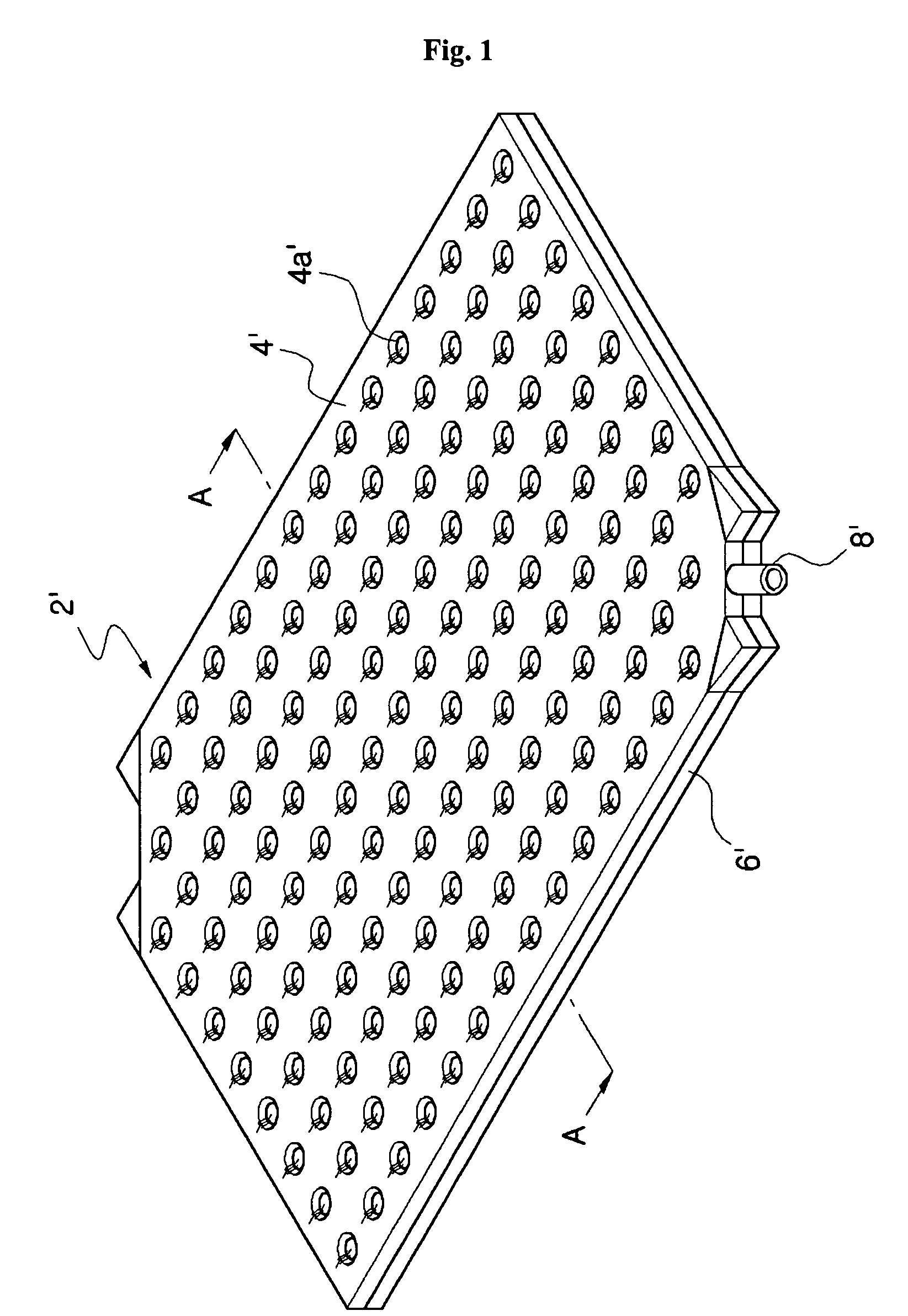
[0010]In order to solve the problems of the conventional heating system as described above, a dry type heating panel made of concrete, synthetic resin, or yellow clay, which is embedded with a pipe for carrying heating water therein, or which is provided with grooves or fixing members for installing the pipe for carrying heating water, was developed. The dry type heating panel is an assembly type heating panel, and has advantageous effects in that the construction of the heating system may be completed by simply assembling previously produced dry type panels, thereby reducing the construction time, and simplifying maintenance and repair operations thereof. However, the dry type heating panel has problems in that since it adopts a line heating structure in which radiation heat is mainly concentrated where the pipe for carrying heating water is located, generating a severe temperature variation in the heating system, the dry type heating panel is ineffective in view of heating efficiency, and in that since the pipe itself is made of metal or synthetic resin, it is expensive, resulting in increased construction costs. Furthermore, thermal loss may occur due to piping, and dewing phenomenon may occur on the surface of the pipe, thereby wetting the panel.
[0011]In order to solve the problems of the conventional dry type heating panel described above, as disclosed in U.S. Pat. No. 5,080,166 and Korean Patent Laid-open publication No. 2002-95733, a plate type heating panel provided with an inner fluid pathway for allowing the heating water to flow therethrough was developed. Compared with the dry type heating system adopting the line heating structure, the plate type heating panel having the inner fluid pathway therein adopts a plane heating structure in which the heating water flows not in a local area but in an overall area, so that it has very high heating efficiency, resulting in reduction of fuel expenses, and so that the pipe is not required for the structure of the plate type heating panel, thereby eliminating a complicated piping work and reducing the expenses for piping. Additionally, the plate type heating panel is not subject to the thermal loss and the dewing phenomenon, which usually occurs on the surface of the pipe in the structure of the dry type heating panel, and allows a weight of the panel to be reduced. Furthermore, the plate type heating panel is very easy to construct and repair.
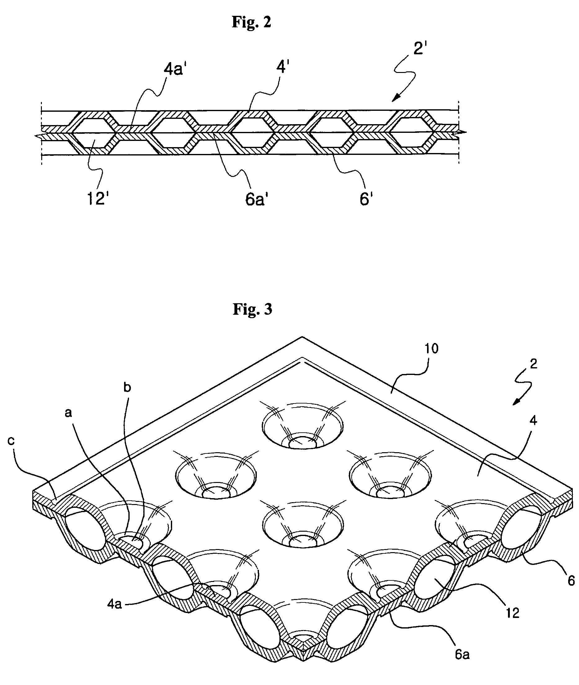
[0012]However, as shown in FIG. 2, a conventional plate type heating panel 2′ having the inner fluid pathway has a disadvantage in that since the inner fluid pathway 12′ has a hexagonal shape, it is structurally very weak at an angled portion of the hexagonal shape. Furthermore, compared with an individual heating system in which the heating fluid has a water pressure of 3.5 kgf / cm2 or less as a maximum value, in case of a central heating or a district(regional) heating, the heating fluid has a water pressure of about 6 to 7 kgf / cm2 as a maximum value, and may have a local water pressure over 6 to 7 kgf / cm2 due to a site or height of the building. Accordingly, when installing the inner fluid pathway-embedded heating panel in the central heating or in the district heating, a pressure resistance of the heating panel must be considered in order to prevent a deformation or leakage of the panel, which may be caused by the water pressure condition as mentioned above.
[0013]Japanese Utility Model Laid-open Publication No. (Sho)51-69458 discloses a bottom heating type panel using heating water, which comprises a heat insulating bottom panel with zigzag-shaped grooves formed thereon, a pipe for carrying heating water fixed to the zigzag-shaped grooves, and a metal plate for heat radiation formed on the heat insulating bottom panel while contacting the pipe for carrying heating water. However, since the bottom heating type panel employs the line heating structure, it has a low thermal efficiency, and regardless of double floors in a floating structure, it has a low sound absorbing performance due to absence of sound absorbing / vibration isolating layers.
[0014]Korean Patent Laid-open Publication No. 1995-6363 discloses an assembly type ondol plate having an inner heating water pathway. However, the inner heating water pathway of the ondol plate also has a hexagonal shape, and thus it is structurally very weak at an angled portion of the hexagonal shaped inner heating water pathway.DISCLOSURE

Problems solved by technology

Accordingly, the conventional ondol heating system has problems due to the structure thereof as follows.
First, due to poor heat insulating effect of the porous concrete layer 16 and the heat insulating layer 18′, the conventional heating system has a low thermal efficiency.
For instance, in the structure of the heating system shown in FIG. 13, the heating water having a temperature of about 70˜80° C. must be supplied from a heating water supplier to the heating system in order to heat the floor surface of the room to a temperature of about 30° C., leading to a large thermal loss.
Therefore, the conventional heating system is disadvantageous in view of energy consumption.
Second, since the noise and vibration cannot be effectively prevented from being transmitted to an upper portion only with the porous concrete layer 16, the conventional heating system is weak in sound absorbing function, and thus, it cannot satisfy sound absorbing requirements for residential constructions, particularly, such as apartments.
Furthermore, when there occurs a problem in the pipe 13, such as a water leakage, the mortar layer 14 must be broken in order to repair the pipe 13, thereby making it difficult to repair the heating system, and requiring a large expenditure for repairs.
However, the dry type heating panel has problems in that since it adopts a line heating structure in which radiation heat is mainly concentrated where the pipe for carrying heating water is located, generating a severe temperature variation in the heating system, the dry type heating panel is ineffective in view of heating efficiency, and in that since the pipe itself is made of metal or synthetic resin, it is expensive, resulting in increased construction costs.
Furthermore, thermal loss may occur due to piping, and dewing phenomenon may occur on the surface of the pipe, thereby wetting the panel.
However, as shown in FIG. 2, a conventional plate type heating panel 2′ having the inner fluid pathway has a disadvantage in that since the inner fluid pathway 12′ has a hexagonal shape, it is structurally very weak at an angled portion of the hexagonal shape.
However, since the bottom heating type panel employs the line heating structure, it has a low thermal efficiency, and regardless of double floors in a floating structure, it has a low sound absorbing performance due to absence of sound absorbing / vibration isolating layers.
However, the inner heating water pathway of the ondol plate also has a hexagonal shape, and thus it is structurally very weak at an angled portion of the hexagonal shaped inner heating water pathway.

Method used


Image

  • Heating system of floating structure including heating panel having round to elliptic inner fluid pathway
  • Heating system of floating structure including heating panel having round to elliptic inner fluid pathway
  • Heating system of floating structure including heating panel having round to elliptic inner fluid pathway

Examples


first embodiment

[0069]FIG. 8 is a cross sectional view illustrating a heating system according to the present invention. As shown in the drawings, a heating system 1 is formed at a lower portion of the heating panel 2 with a thermal insulating layer 18 made of EPS (Expanded Polystyrene) to minimize thermal loss, and provided with a metal plate 20 and a finishing material 22 on the heating panel 2.

[0070]The metal plate 20 is made of steel plate, more preferably aluminum coated steel plate, both of which have a high thermal conductivity. Accordingly, an excellent thermal conductivity of the metal plate 20 improves a heat conducting function of the heating panel 2, enhancing the heating efficiency. Furthermore, the metal plate 20 strengthens the heating panel 2, more securely supporting a load applied to the bottom of a building, and uniformly covers an uneven surface of the heating panel, enabling the finishing material 22 to be more easily installed.

[0071]According to a result of an experiment, the ...

second embodiment

[0078]FIG. 9 is a cross sectional view illustrating a heating system according to the present invention, and FIG. 10 is a partially exploded view illustrating a coupled state of the supporting members and the plate member.

[0079]A floating floor structure 34 of the heating system according to the second embodiment comprises a plate member 36 made of a polymeric resinous panel, such as sheet molding compound (SMC), as well as the wooden material, and a plurality of supporting members 38 clamped to the plate member 36 with screws such that a height of the plate member 36 to the slab 26 can be adjusted.

[0080]That is, as shown in FIG. 10, each of the supporting members 38 is formed with threads on an outer periphery thereof, and the plate member 36 coupled to the supporting members 38 is formed with grooves 36a to which the supporting members 38 are fastened. Furthermore, each of the grooves 36a is formed at an inner surface thereof with threads engaged with the threads of each of the su...


PUM


Abstract

Disclosed herein is a heating system of floating floor structure including a heating panel with a circular or elliptical inner fluid pathway. The heating panel having the circular or elliptical inner fluid pathway overcomes limitation on pressure resistance, which is the problem of the convention heating panel having a hexagonal fluid pathway, thereby providing enhanced pressure resistance. Furthermore, a floating floor structure of the heating system enhances thermal efficiency, and effectively improves sound absorbing / dampening function in a floor of a building. Additionally, the floating floor structure is provided with inner spaces, which allow utility equipment, such as an electric wire or a pipe, to be easily established therein, thereby enabling an easy repair of the heating system and the utility equipment.

Description

TECHNICAL FIELD[0001]The present invention relates to a heating system of a floating floor structure including a heating panel with a circular or elliptical inner fluid pathway, and more particularly to a heating system, which includes a plate heating panel having a circular or elliptical inner fluid pathway formed therein, in a floating floor structure, thereby enhancing pressure resistance, sound absorbing and heat insulating functions.BACKGROUND ART[0002]Generally, a heating system, having been applied to residential buildings, such as houses, villas, and apartments, employs a structure involving a wet heating process, in which a pipe is laid under a flooring material of a room in a building and supplied with heating fluid, such as heating water, thereby heating the room of the building. FIG. 13 is a cross sectional view of a so-called wet type ondol heating system of a conventional technique (“ondol” is a Korean traditional floor-embedded heating system).[0003]As shown in FIG. 1...

Claims


Application Information

Patent Timeline
Patent Type & Authority Patents(United States)
IPC IPC(8): F24H1/20F24D3/16
CPCF24D3/14Y02B30/00
Inventor KIM, MUN-SIKPARK, SEONG-CHANHWANG, SUNG-SEOCKKANG, SE-CHANGJANG, DONG-SIKPARK, JANG-SEOK
Owner LG CHEM LTD
Why Eureka
Eureka Blog
Learn More