Method of driving plasma display panel
- Summary
- Abstract
- Description
- Claims
- Application Information
AI Technical Summary
Benefits of technology
Problems solved by technology
Method used
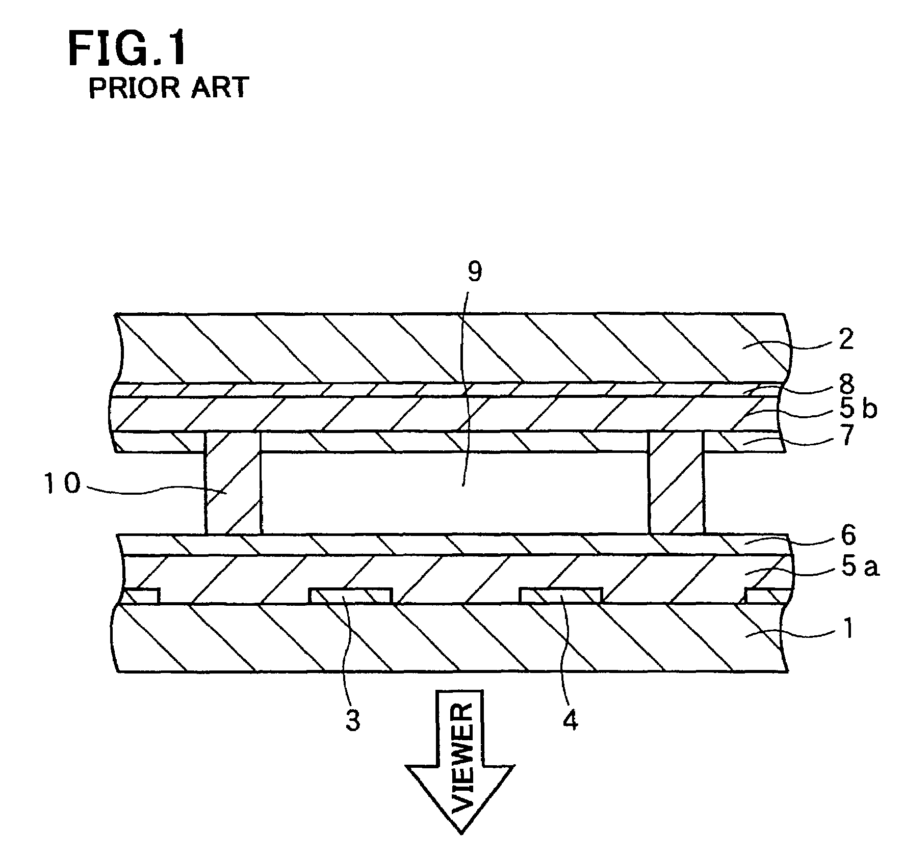
Image

Examples
first embodiment
[First Embodiment]
[0081]Hereinbelow is explained a method of driving a plasma display panel, in accordance with the first embodiment of the present invention, with reference to FIGS. 5A to 5D in which FIG. 5A illustrates a waveform of a pulse to be applied to the sustaining electrode 4 in a preliminary discharge period, FIG. 5B illustrates a waveform of a pulse to be applied to the scanning electrode 3 in a preliminary discharge period, FIG. 5C illustrates a voltage difference between the scanning electrode 3 and the sustaining electrode 4, and FIG. 5D illustrates a waveform of light emitted in a cell as a result of the voltage difference illustrated in FIG. 5C.
[0082]In FIGS. 5A to 5C, Vs indicates a base voltage of both a scanning electrode and a sustaining electrode, and further indicates a voltage amplitude of a sustaining pulse (not illustrated).
[0083]As illustrated in FIG. 5A, a preliminary discharge pulse 11a to be applied to the sustaining electrode 4 falls down from the base...
second embodiment
[Second Embodiment]
[0102]Hereinbelow is explained a method of driving a plasma display panel, in accordance with the second embodiment of the present invention, with reference to FIGS. 7A to 7D in which FIG. 7A illustrates a waveform of a pulse to be applied to the sustaining electrode 4 in a preliminary discharge period, FIG. 7B illustrates a waveform of a pulse to be applied to the scanning electrode 3 in a preliminary discharge period, FIG. 7C illustrates a voltage difference between the scanning electrode 3 and the sustaining electrode 4, and FIG. 7D illustrates a waveform of light emitted in a cell as a result of the voltage difference illustrated in FIG. 7C.
[0103]In the second embodiment, while the preliminary erasing discharge pulse 12 is applied to the scanning electrodes 3, a voltage (Vs+Vpeb) greater than the voltage Vs is applied to the sustaining electrodes 4.
[0104]As illustrated in FIG. 7C, the voltage difference gently falls down to apply a negative voltage difference ...
third embodiment
[Third Embodiment]
[0111]Hereinbelow is explained a method of driving a plasma display panel, in accordance with the third embodiment of the present invention, with reference to FIGS. 8A to 8D in which FIG. 8A illustrates a waveform of a pulse to be applied to the sustaining electrode 4 in a preliminary discharge period, FIG. 8B illustrates a waveform of a pulse to be applied to the scanning electrode 3 in a preliminary discharge period, FIG. 8C illustrates a voltage difference between the scanning electrode 3 and the sustaining electrode 4, and FIG. 8D illustrates a waveform of light emitted in a cell as a result of the voltage difference illustrated in FIG. 8C.
[0112]The third embodiment is different from the second embodiment in that a pulse (Vs+Vpeb) to be applied to the sustaining electrodes 4 in synchronization with the preliminary erasing discharge pulse 12 is terminated while the preliminary erasing discharge pulse 12 is falling down at its leading edge, and a pulse to be appl...
PUM
 Abstract
Description
Claims
Application Information
 - R&D
- Intellectual Property
- Life Sciences
- Materials
- Tech Scout
- Unparalleled Data Quality
- Higher Quality Content
- 60% Fewer Hallucinations
Browse by: Latest US Patents, China's latest patents, Technical Efficacy Thesaurus, Application Domain, Technology Topic, Popular Technical Reports.
© 2025 PatSnap. All rights reserved.Legal|Privacy policy|Modern Slavery Act Transparency Statement|Sitemap|About US| Contact US: help@patsnap.com