Eureka AIR delivers breakthrough ideas for toughest innovation challenges, trusted by R&D personnel around the world.

Method of and apparatus for acquiring data of dynamic physical processes via a radio link

Inactive Publication Date: 2006-04-11
REINDL LEONHARD
View PDF13 Cites 8 Cited by
  • Summary
  • Abstract
  • Description
  • Claims
  • Application Information

AI Technical Summary

Benefits of technology

[0007]The novel method, apparatus and system are more simple, no energy storing unit is required, and also a continuous wave (CW) exciting wave having one single frequency can be used. With the novel method, apparatus and system, a sampling rate which is only necessary to resolve the dynamics of the measurement value is sufficient. On the other hand, the invention presented here is restricted to measurement tasks in which the measurement values have a sufficient high dynamic variation in time to produce a sufficient high frequency shift between the exciting wave and the sensor wave which are in the following also referred to as the read-out signal and the sensor signal.
[0018]The preferred frequency range for the read-out signal is in the UHF and VHF region to reduce the size of the antennas, but the invention is also applicable in all other frequency ranges. In ranges of higher frequencies the Doppler shift may move towards the modulated spectral components, thus complicating the analysis.
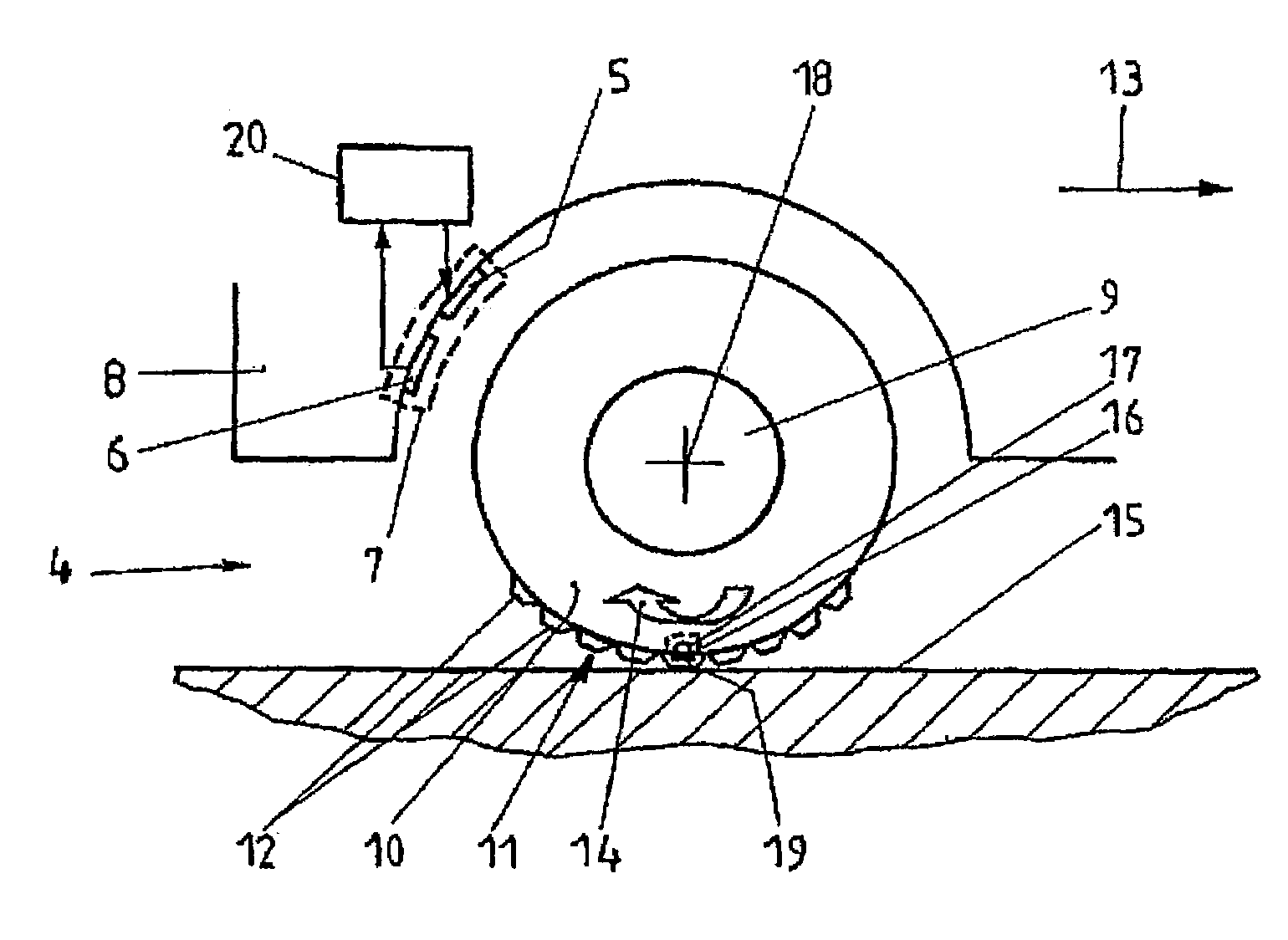
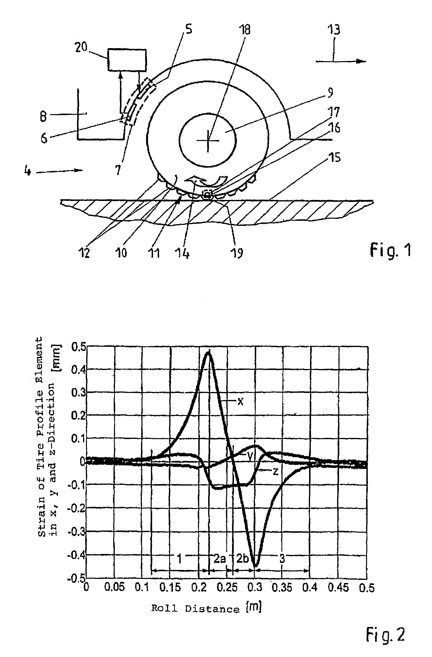
[0020]The radio transponder unit including the sensor and the transponder antenna may have a very simple structure. For example, both the sensor and the transponder antenna may be made up of one conductive wire section which is bent to different shapes and which changes at least one of its electrical properties due to the bending. By using such conductive wire sections for monitoring the strain of a tire element during its contact with the roadway while the corresponding vehicle is moving the friction coefficient of this tire with the road can be estimated. Such a sensor tire or “intelligent tire” can easily and economically be produced in series.

Problems solved by technology

A continuous wave (CW) signal containing one single frequency could not be used because this would destroy the time domain division.

Method used


Image

  • Method of and apparatus for acquiring data of dynamic physical processes via a radio link
  • Method of and apparatus for acquiring data of dynamic physical processes via a radio link
  • Method of and apparatus for acquiring data of dynamic physical processes via a radio link

Examples


example

[0061]Lcontact=8 cm (see FIG. 2) and Acontact=0.45 mm Thus the Doppler shift is increased by approximately 1.8%, which is very hard to detect.

[0062]By processing of the Doppler shift alone no significant measurement signal describing the conditions of during passing the contact area can be extracted. Although the frequency ωLatsch is clearly higher than the turning frequency of the wheel ωwheel, the amplitude Acontact is also significant smaller as compared to the radius of the wheel r.

[0063]Case 3 Circular movement of the wheel with consideration of the modulated back scattering process.

[0064]According to the invention, the strain Acontact·sin (ωcontact·t) is now transformed into a modulation of the frequency of the back-scattered sensor signal. To this end, the electrical parameters of a frequency determining element of the sensor, e.g. a part of the transponder antenna 17, or any load of the transponder antenna 17, is altered at the angular frequency ωcontact. This can be achieve...


PUM


Abstract

For acquiring data of dynamic physical processes via a radio link, a transponder antenna (17) is excited by an electromagnetic exciting wave at the resonance frequency of the transponder antenna (17), and a back-scattered electromagnetic sensor wave which is modulated by a sensor (16) having an electrical impedance depending on the data to be acquired is received and analyzed. The sensor (16) is directly connected to the transponder antenna (17) such that the sensor changes the electrical impedance of the transponder antenna (17) with every variation of the data to be acquired. The electromagnetic wave which is back-scattered by the transponder antenna (17) is received as the sensor wave at the same time as the transponder antenna (17) is excited by the exciting wave.

Description

CROSS REFERENCE TO RELATED APPLICATIONS[0001]This application is a continuation of International Application PCT / EP01 / 13359 with an International Filing Date of Nov. 19, 2001 and claiming priority to co-pending German Patent Application No. 100 57 059.3 entitled “Verfahren und Vorrichtung zur Messwertüberwachung durch Frequenzanalyse von modulierter Rückstreuung”, filed on Nov. 17, 2000.FIELD OF THE INVENTION[0002]The present invention generally relates to a method and an apparatus for acquiring data of dynamic physical processes via a radio link. The present invention relates to wireless reading out a sensor to acquire data of a dynamic physical process which may also be referred to as measurement values. Especially, the present invention relates to such methods and apparatuses in which neither the sensor including the time-varying electrical impedance nor the transponder antenna associated with the sensor include an own power supply to produce the sensor wave which encodes the dat...

Claims


Application Information

Patent Timeline
IPC IPC(8): B60C23/00B60T8/00G01S13/00G01N19/02B60C23/06B60T8/172H04B1/59
CPCB60C23/0444B60T8/1725B60T2240/03
Inventor REINDL, LEONHARD
Owner REINDL LEONHARD
Why Eureka
Eureka Blog
Learn More