Hammermill with stub shaft rotor apparatus and method

a rotor and hammermill technology, applied in the field of hammermills, can solve the problems of material reduction and gradual diminution, and achieve the effects of reducing the maximum bending stress, improving the stiffness of the rotor shaft, and efficient structural design

Active Publication Date: 2006-04-11
CARTER DAY INDS
View PDF3 Cites 6 Cited by
  • Summary
  • Abstract
  • Description
  • Claims
  • Application Information

AI Technical Summary

Benefits of technology

[0011]An object and advantage of the invention is to provide a hammermill with a more efficient structural design by eliminating the solid rotor shaft.
[0012]Another object and advantage of the invention is to provide a hammermill with a reduced maximum bending stress in the rotor shaft.
[0013]Another object and advantage of the invention is to provide a hammermill with an increased stiffness in the rotor shaft.
[0014]Another object and advantage of the invention is to provide a hammermill that is less sensitive to vibration.
[

Problems solved by technology

The material is initially impacted by the hammers, which may cause some material reduction.
The rotating hammers continue to pulverize the material downstream of

Method used


Image

  • Hammermill with stub shaft rotor apparatus and method
  • Hammermill with stub shaft rotor apparatus and method
  • Hammermill with stub shaft rotor apparatus and method

Examples


Embodiment Construction

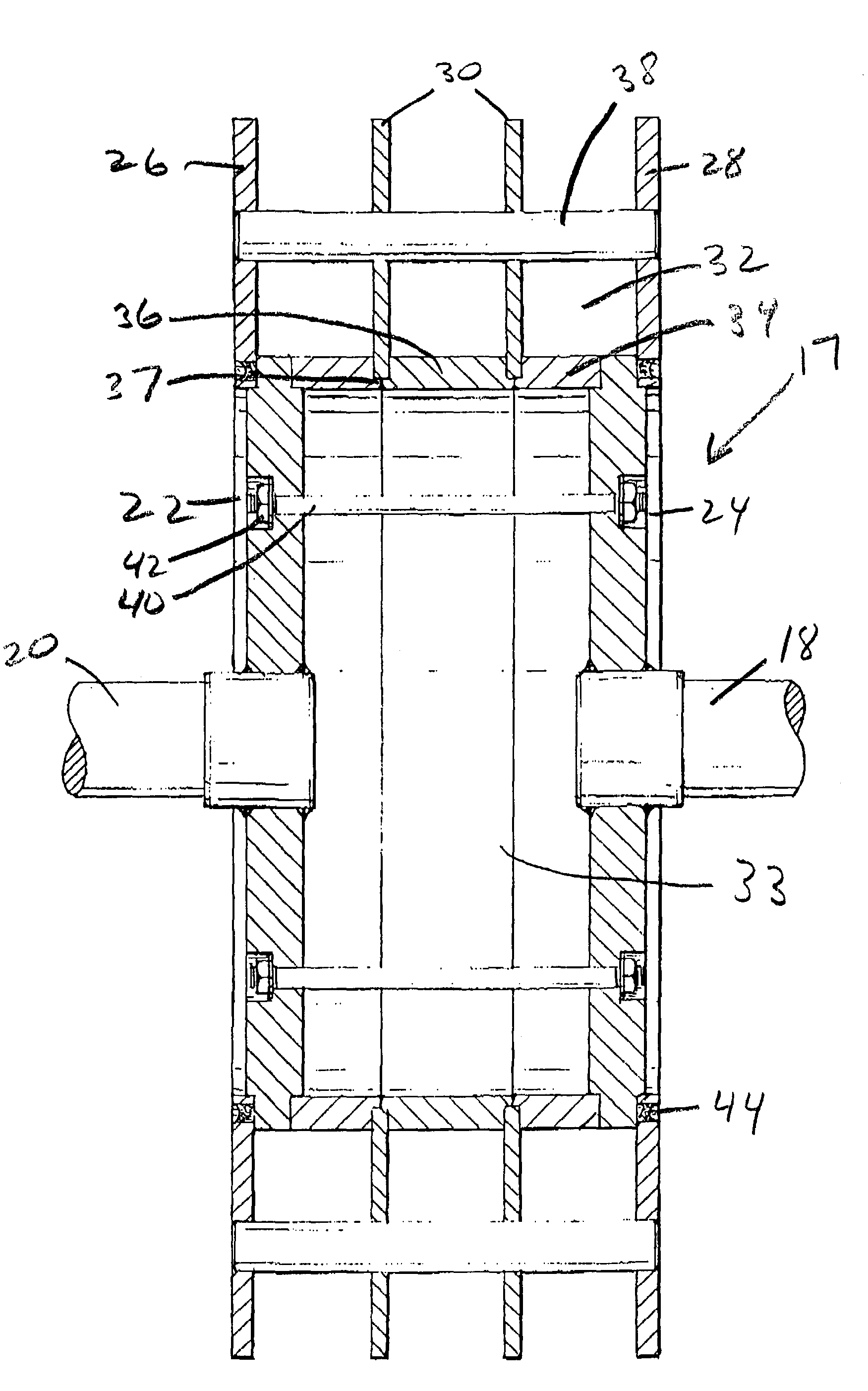
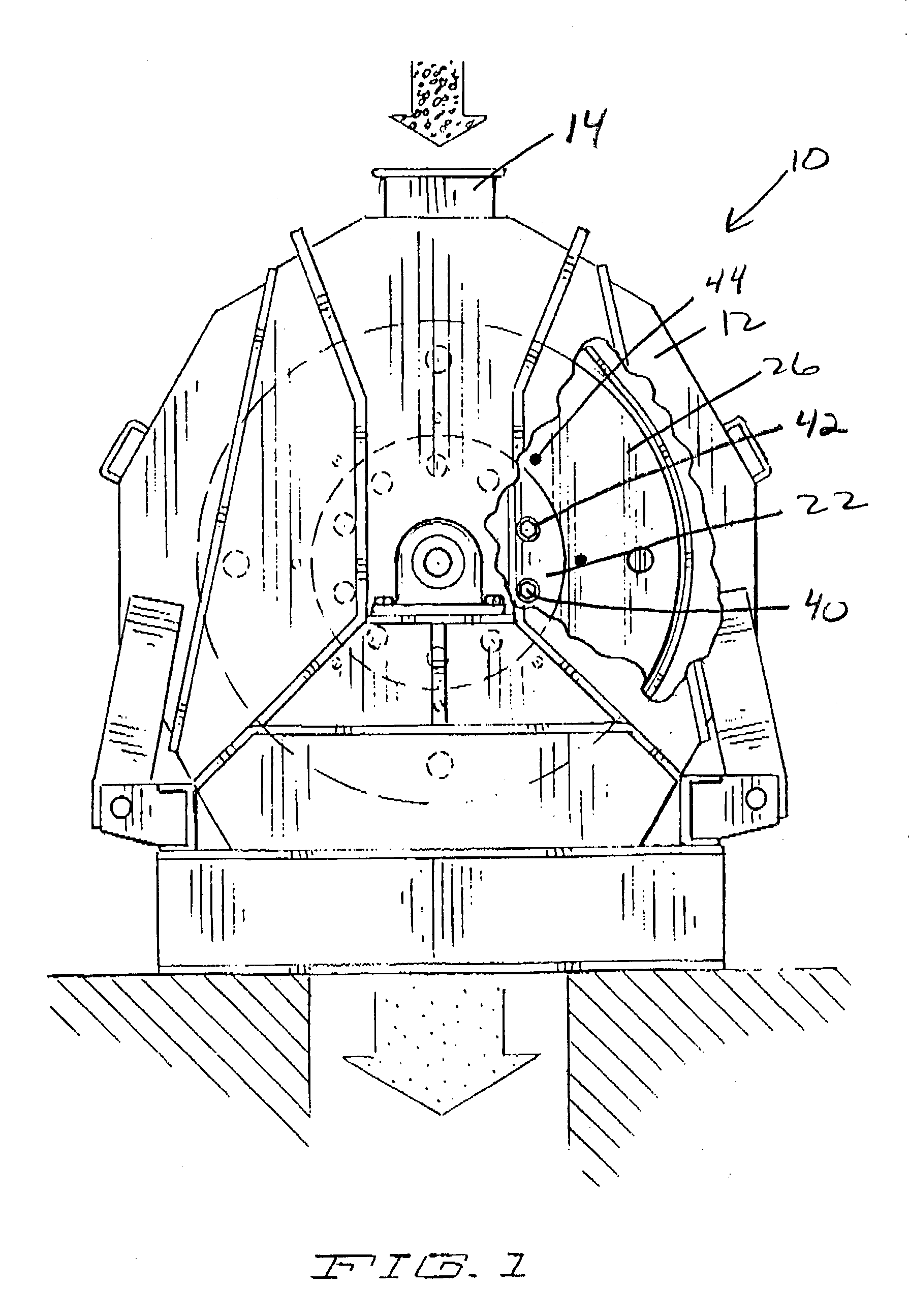
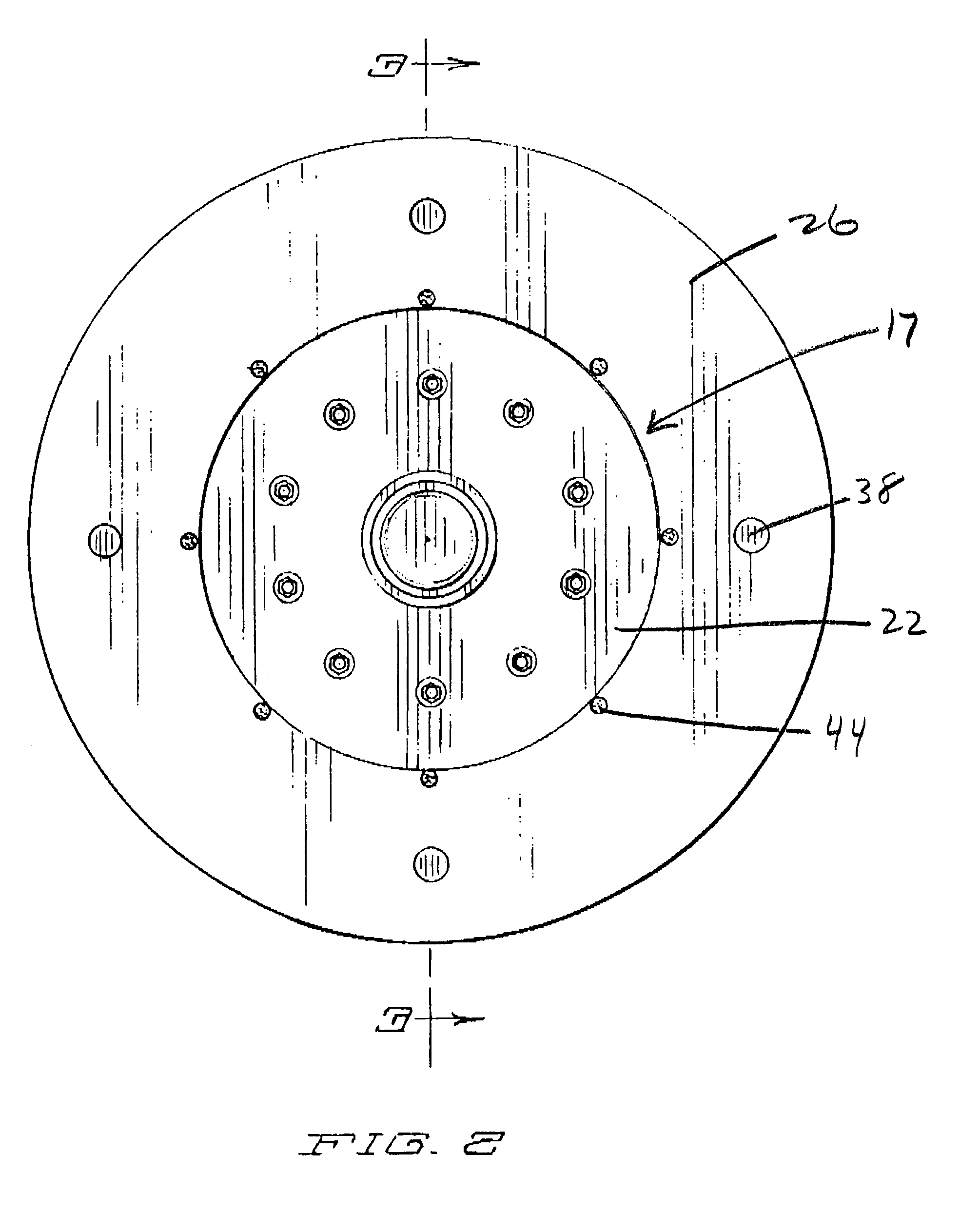
[0021]With reference to the accompanying Figures, which provide one embodiment of the invention, there is provided a hammermill (10) for comminuting material, having a housing (12), material inlet (14), and particle discharge (16). FIG. 2 shows the rotor shaft assembly (17). The inventive tubular rotor shaft assembly (17) has an axis of rotation and comprises a driven stub rotor shaft (18), a support stub rotor shaft (20), a first flange plate (22) and a second flange plate (24), spacer rings (32), tie rods (40) and tie rod nuts (42).

[0022]Turning specifically to FIG. 3, the invention comprises a driven rotor stub shaft (18) that is drivingly connected to an engine or known other means for rotating the shaft, and a support rotor stub shaft (20) that is mounted to a bearing or similar structure that is not shown in the Figures. A first flange plate (22) is rigidly attached to the support rotor stub shaft (20) and a second flange plate (24) is attached to the driven rotor stub shaft (...


PUM

PropertyMeasurementUnit
Diameteraaaaaaaaaa
Tensionaaaaaaaaaa

Abstract

An improved rotor design for hammermills. The invention eliminates the solid rotor shaft and replaces it with a tubular structure comprised of two stub rotor shafts with plate flanges and grooved spacer rings therebetween. End head disks, attached to the plate flanges, and intermediate disks are concentrically positioned with the axis of rotation of the assembly. The intermediate disks are held in alignment by the pilot groove located in the spacer rings. The flanges, stub shafts, spacer rings and intermediate disks are supported and held in proper alignment by tension rod compression. The resulting tubular rotor shaft assembly is less massive, more stiff, less susceptible to vibration, has a reduced bending stress, is less expensive to startup and operate and less expensive and more flexible in terms of component inventory than known solid through-shaft rotors.

Description

FIELD OF THE INVENTION[0001]This invention relates generally to hammermills.BACKGROUND OF THE PRESENT INVENTION[0002]Hammermills have long been used for grinding or comminution of materials. Typically hammermills consist of a rotor mounted on a solid through rotor shaft inside a housing. A material inlet is generally located at the top of the housing with one or more material outlets located near the bottom of the housing. The rotor includes a solid through drive shaft and rows of hammers which are normally flat steel blades or bars. A steel rod or pin pivotably connects the hammer to the rotor. The rotor is mounted inside a typically teardrop shaped enclosure, commonly known as a grinding or working chamber, which is comprised of a cutting plate mounted on either side of the material inlet for reversible hammermills. Reversible hammermills are capable of rotation in either direction, a feature which provides for increased life for the hammers, cutting plates and screen plates. The ...

Claims


Application Information

Patent Timeline
IPC IPC(8): B02C13/26B02C13/04B02C13/28
CPCB02C13/04B02C13/26B02C13/28Y10T29/49895Y10T29/49948Y10T29/49899Y10T29/49874Y10T29/49863
Inventor HAUCH, DAVID
Owner CARTER DAY INDS
Why Eureka
Try Eureka