
Plastic window assembly

a window and plastic technology, applied in the direction of door/window protective devices, parallel plane units, instruments, etc., can solve the problems of increasing the cost of a window dramatically, and prohibitively expensive for most construction projects, so as to eliminate the marring of the window pane, reduce the time, and facilitate the installation. low cost

Inactive Publication Date: 2006-04-11
HEADWATERS INC AS GRANTOR +4
View PDF26 Cites 15 Cited by
  • Summary
  • Abstract
  • Description
  • Claims
  • Application Information

AI Technical Summary

Benefits of technology

[0010]The plastic window assembly of the subject invention provides for easy low cost installation by providing a pre-assembled window assembly that can be installed into an opening of a structure in reduced time and without skilled craftsman. Further, the plastic window assembly provides for the installation of a plastic muntin between window panes that eliminates marring of the window panes.

Problems solved by technology

This is a time consuming process that is further complicated when a unique shaped window is required.
The time required for a skilled tradesman to miter cut pieces for a unique shaped window increases the cost of a window dramatically to the point of being prohibitively expensive for most construction projects.
Irregularities or waviness on the flat part of the muntin that abuts the window will cause an unpleasing appearance and destroy the wooden window look desired.
Further, the plastic muntin may mar the window panes or leave marks on the window that cannot be removed once the window is assembled.

Method used


Image

  • Plastic window assembly
  • Plastic window assembly
  • Plastic window assembly

Examples


Embodiment Construction

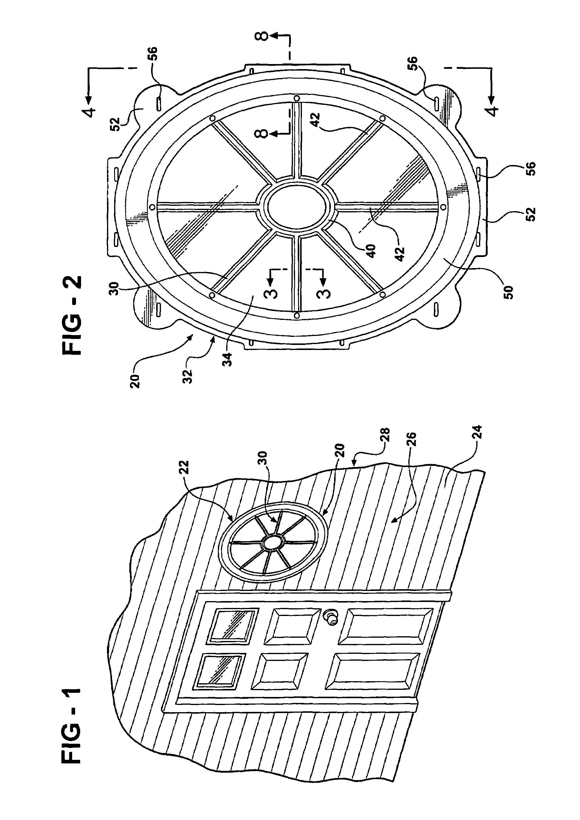
[0027]Referring to the Figures, wherein like numerals indicate like or corresponding parts throughout the several views, a plastic window assembly is generally indicated at 20. Referring to FIG. 1, the plastic window assembly 20 is adapted to be mounted in an opening 22 defined by a structure 24. The structure 24 has exterior and interior surfaces 26 and 28. The plastic window assembly 20 may be installed in any desired location within the structure 24.

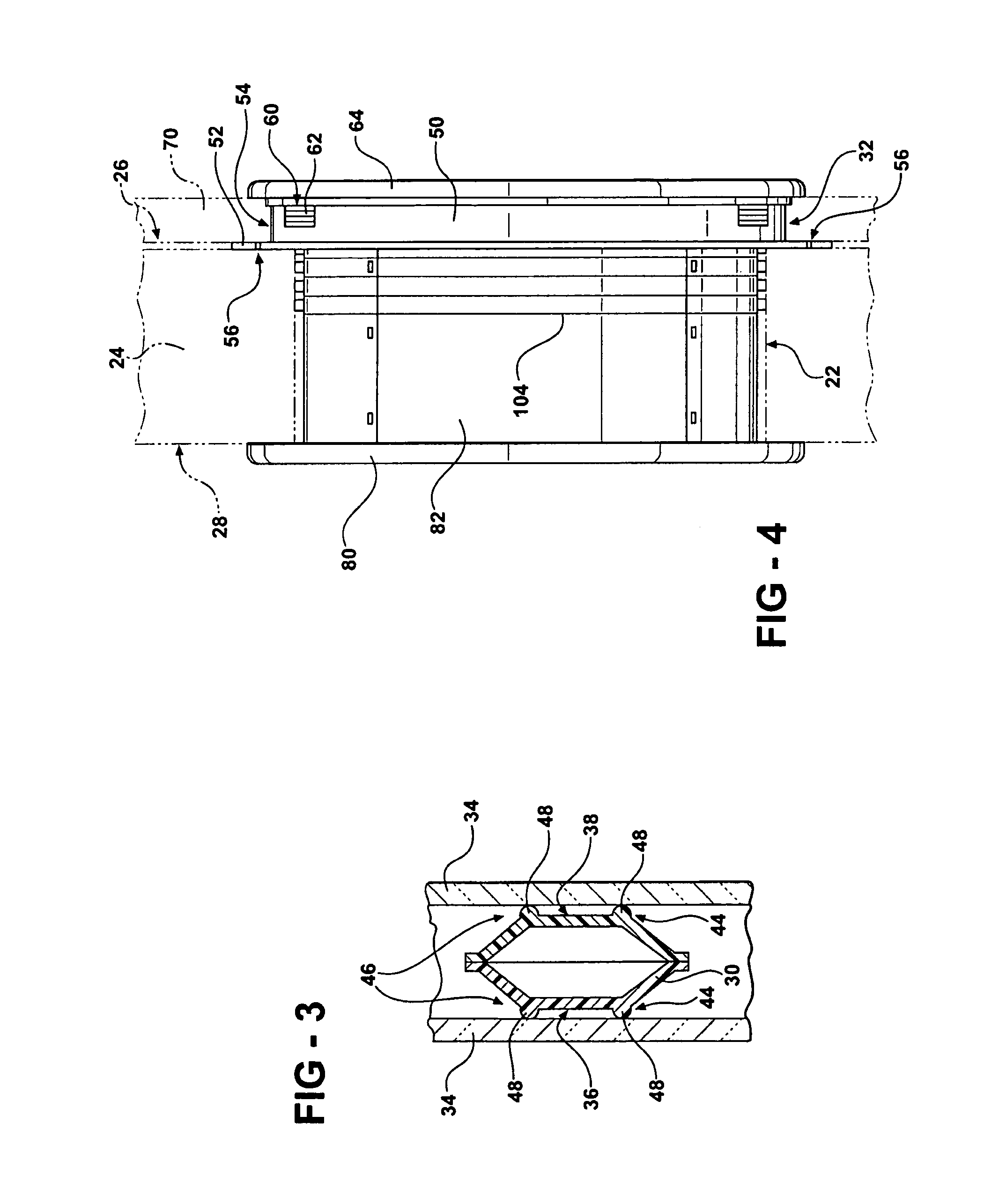
[0028]Referring to FIG. 2, the plastic window assembly 20 is oval shaped with a decorative plastic window muntin 30. Although the preferred embodiment is oval shaped, the plastic window may be shaped in any continuous curvilinear form. Further the plastic window assembly may also be annular in shape. The plastic window assembly 20 includes a plastic frame 32 that supports parallel window panes 34. The window muntin 30 is disposed between the parallel window panes. The window muntin 30 includes a central portion 40 and a plurality of b...


PUM


Abstract

A plastic window assembly is adapted to be mounted in an opening defined by a structure. The plastic window assembly is oval-shaped with a decorative plastic window muntin. A plastic frame supports parallel window panes. The window muntin is disposed between the parallel window panes. Flat surfaces of the window muntin have a first edge and a second edge and include a ridge disposed along each of the edges. Marring of the window panes is prevented because the ridge provides for line contact between the window muntin and the window panes. The window muntin may also be integrally molded to a plastic pane disposed between the parallel panes of glass. The plastic pane includes a surface texture that simulates frosted glass. The plastic window assembly includes a plurality of liner panels that extend through the opening from an interior of the structure. The window assembly includes a flange having aperture throughwhich fasteners are inserted to secure the window assembly to the structure. An exterior trim ring attaches to the outside of the window assembly and over siding on the structure. An interior trim ring attaches to a flange in the liner panel to give a finished appearance. All exposed surfaces include a surface texture that simulates wood grain.

Description

[0001]The present application is a continuation application of U.S. patent application Ser. No. 09 / 724,093, filed Nov. 28, 2000, now U.S. Pat. No. 6,606,333.BACKGROUND OF THE INVENTION[0002]1. Field of the Invention[0003]A plastic window assembly adapted to be mounted in an opening defined by a structure.[0004]2. Description of the Prior Art[0005]A conventional construction method of installing a window into a structure requires the efforts of a skilled tradesman. The skilled tradesman will build an opening to fit the window, and proceed to cut a plurality of mitered pieces to construct the window. This is a time consuming process that is further complicated when a unique shaped window is required. The time required for a skilled tradesman to miter cut pieces for a unique shaped window increases the cost of a window dramatically to the point of being prohibitively expensive for most construction projects.[0006]A low cost easy to assembly and install window is disclosed in the U.S. P...

Claims


Application Information

Patent Timeline
IPC IPC(8): E06B3/66E06B3/68G07F17/32G07F17/34
CPCG07F17/32G07F17/3216G07F17/34G07F17/3267G07F17/3244
Inventor SCHIEDEGGER, CHARLES EALLEN, CLYDE G.TESLUK, JOHN R.
Owner HEADWATERS INC AS GRANTOR
Learn More