Method and apparatus for monitoring blind fastener setting

a technology for blind fasteners and setting devices, applied in the direction of coupling device connections, manufacturing tools, instruments, etc., can solve the problems of not being able to visually inspect to determine a correctly completed joint, introducing an additional manufacturing step and associated expense into the manufacturing procedure, and not being able to visually inspect to determine if an incorrectly sized rivet has been used in a particular hole diameter

Inactive Publication Date: 2006-04-11
NEWFREY
View PDF37 Cites 23 Cited by
  • Summary
  • Abstract
  • Description
  • Claims
  • Application Information

AI Technical Summary

Benefits of technology

[0022]The method as previously described, may be further used to determine wear on a set of jaws of a fastener setting tool by comparing the mandrel entry time against a pre-determined mandrel entry time. Here, if the fastener setting tool jaws are subject to wear then they may slip when engaging a mandrel stem of the fastener thus delaying the fastener setting cycle load being applied such

Problems solved by technology

However, one of the disadvantages of a blind rivet setting is that the blind side of the set rivet is often inaccessible and therefore cannot be visually inspected to determine a correctly completed joint.
Additionally, even if visual inspection was possible, for rivet setting operations utilising a plurality of blind rivets of different sizes for insertion in different sized holes, a visual inspection may also fail to identify if an incorrectly sized rivet has been used in a particular hole diameter.
A secondary operation of visually or manually inspecting an assembly following a preset automated blind rivet setting operation would introduce an additional manufacturing step and associated expense into the manufacturing procedure.
Whilst both the aforementioned analysis techniques provide a very thorough and effective means of determining the quality of a set blind rivet, both employ complex analytical techniques in order to determine the quality of the setting operation, usually by monitoring step by step, almost continuously, the resulting load/pressure-displacement curve, requiring complex software to effect such analysis adding considerable cost to the rivet setting equipm

Method used


Image

  • Method and apparatus for monitoring blind fastener setting
  • Method and apparatus for monitoring blind fastener setting
  • Method and apparatus for monitoring blind fastener setting

Examples


Embodiment Construction

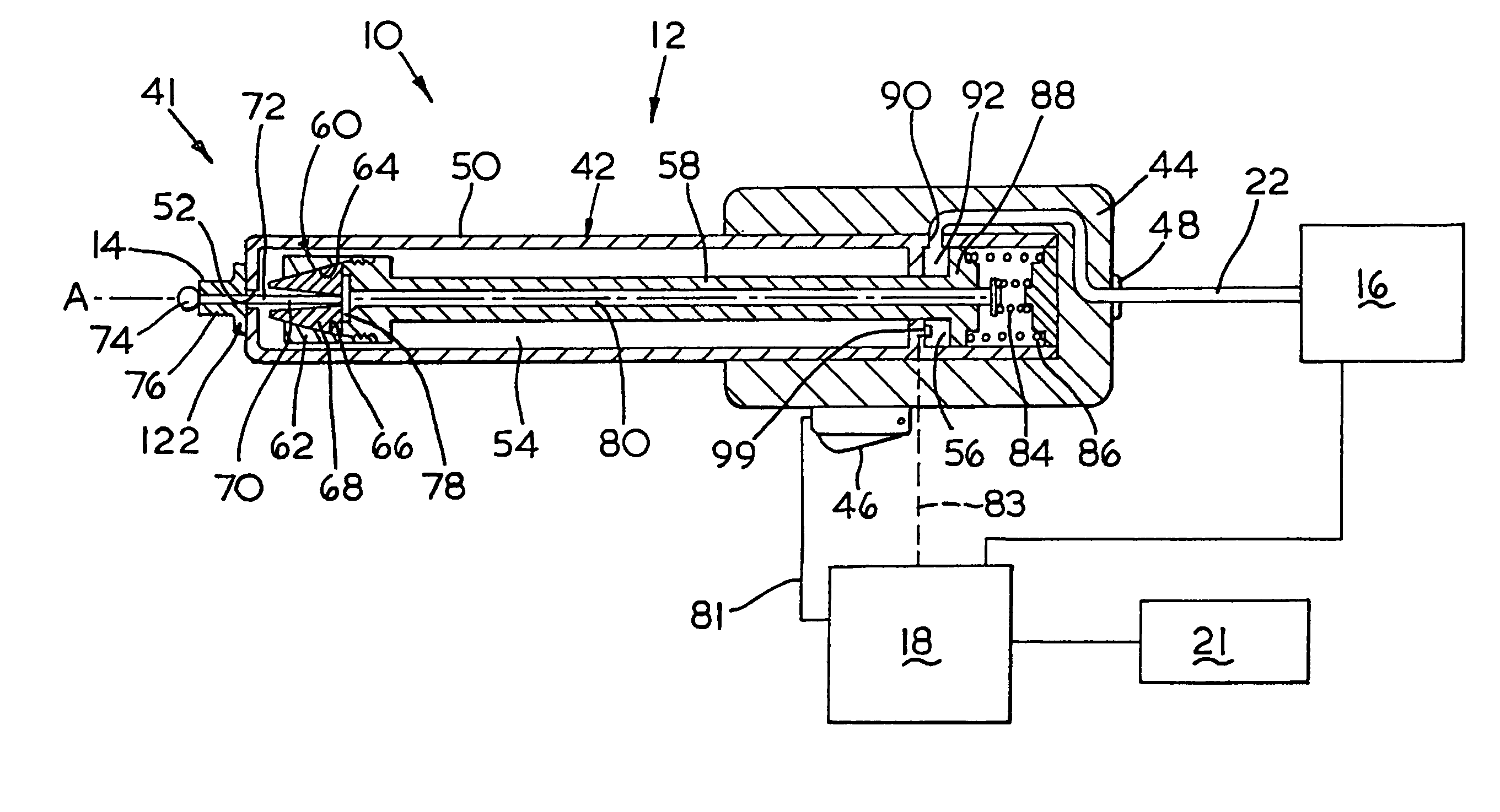
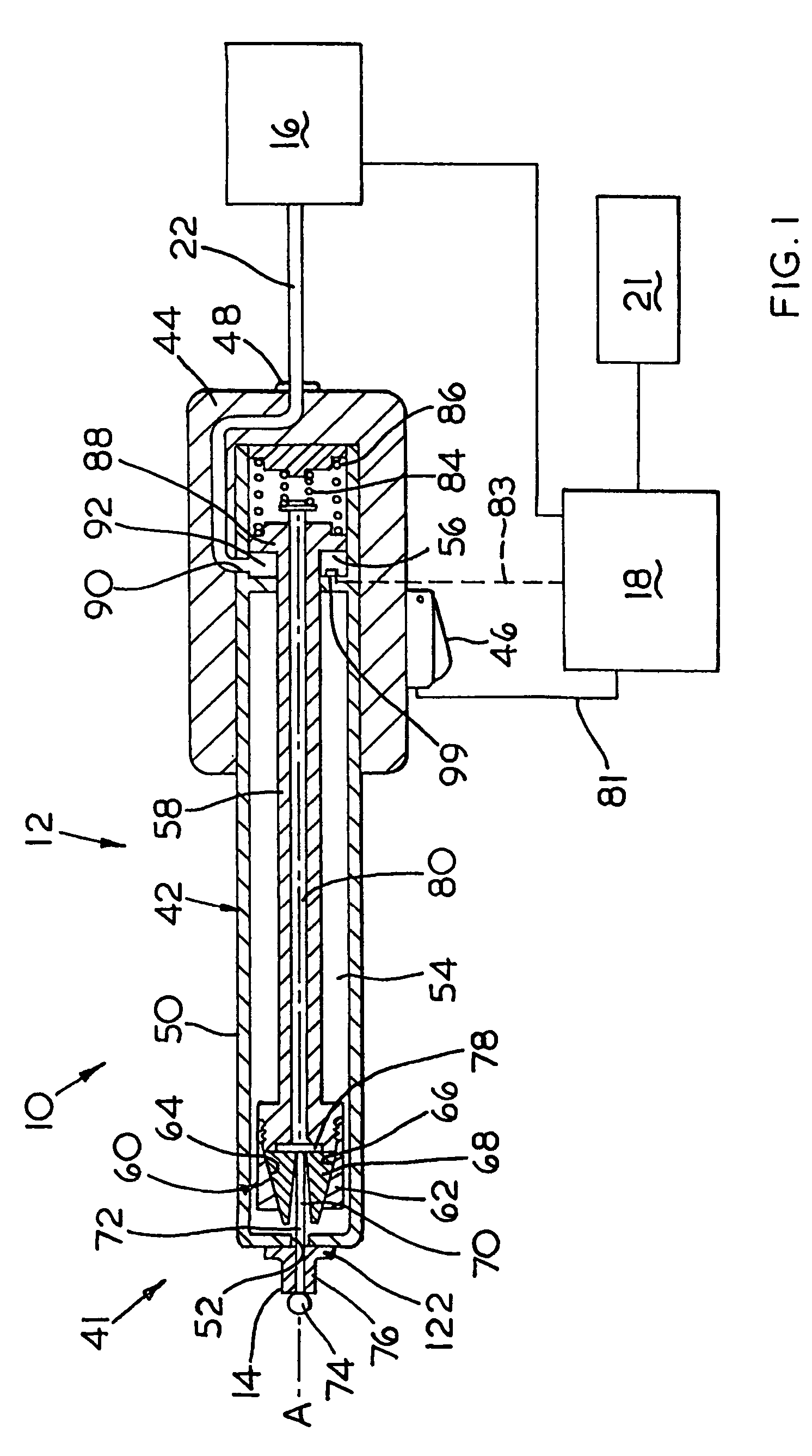
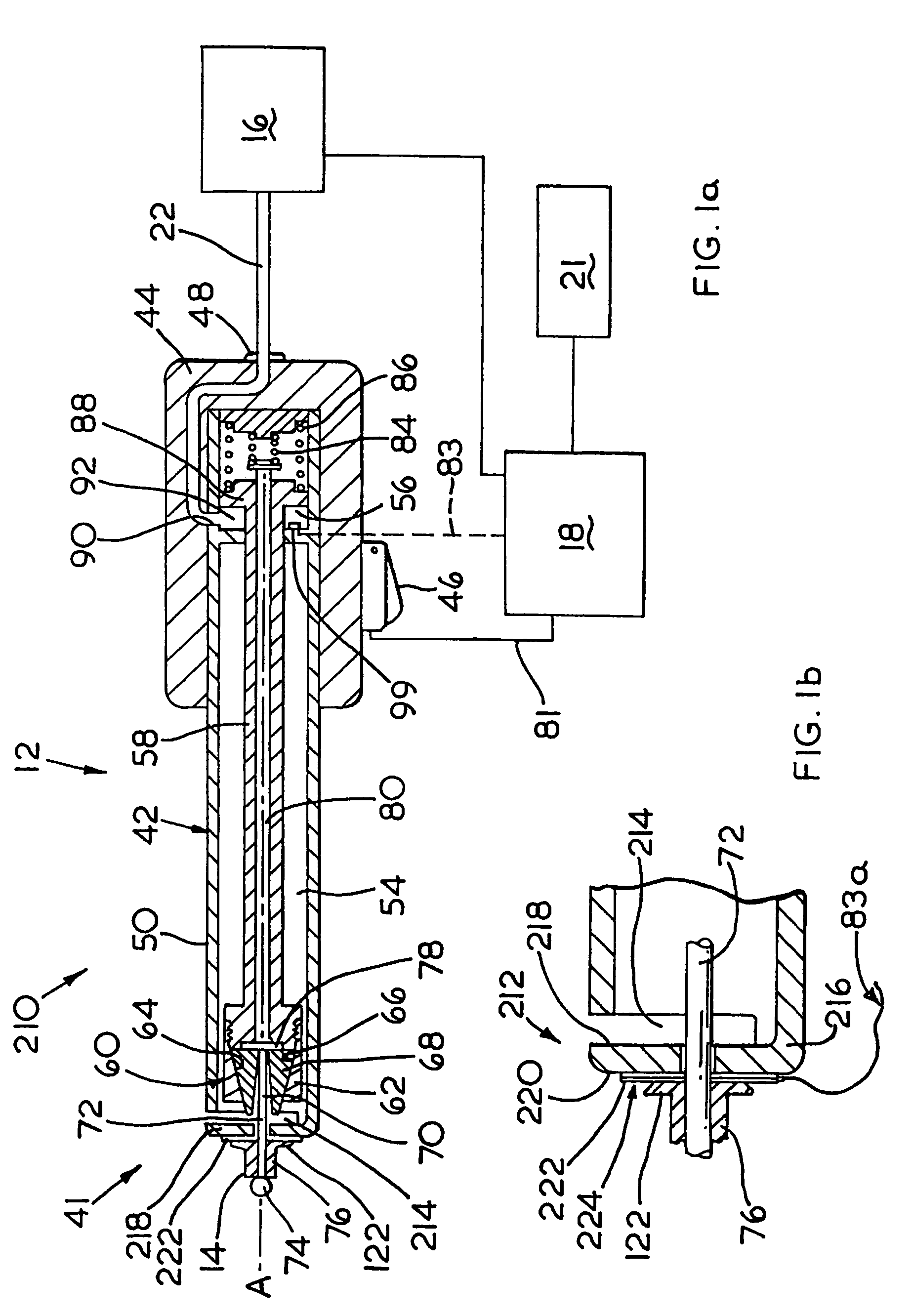
[0033]Referring now to FIG. 1, a conventional blind rivet setting tool is schematically illustrated. A blind rivet setting system (10) comprises a rivet setting tool (12) for setting a blind rivet (14) a hydraulic intensifier (16) and system control circuit shown schematically as (18). The intensifier (16) may be any one of a number of conventional such intensifiers commonly used within the art but may simply be considered as a fluid pressure source for controllably applying pressure to the setting tool (12) by means of hydraulic fluid transferred via a fluid connection pipe (22). Often, intensifiers (16) of this type employ a pressure source, such as pressurised air applied to a cylinder, to compress a hydraulic oil or fluid to transfer fluid pressure to the setting tool. The fluid contained in the intensifier (16) may be considered to be in continuous fluid communication, through pipe (22), with the rivet setting tool (12).

[0034]The tool (12) comprises an elongated body generally ...


PUM

PropertyMeasurementUnit
Timeaaaaaaaaaa

Abstract

A method of monitoring the setting operation for a blind fastener comprising the step of measuring, as a function of time, an electronic signal indicative of the load being applied to the fastener during the setting operation and, from which, determining a mandrel entry load and associated mandrel entry time from this measured signal and an associated setting time, subsequently determining the time difference between the mandrel entry time and the setting time and comparing this time difference against a predetermined reference time difference associated with that particular fastener type to determine whether the set fastener complies with predetermined acceptable setting procedures.

Description

FIELD OF THE INVENTION[0001]The present invention relates to an improved method and apparatus which is capable of monitoring the application and setting of blind fasteners. More particularly, the present invention is directed towards apparatus for monitoring the sequential application and setting of such blind fasteners.BACKGROUND AND SUMMARY[0002]Conventional blind fasteners, such as blind rivets, comprise an outer tubular shell having an enlarged flange at one end, together with a mandrel associated therewith, such mandrel comprising a cylindrical stem extending through the tubular body so as to be co-axial therewith and the stem being coupled with a remote end of the body, usually by having a radially enlarged head at one end for engagement with an end-face (tail end) of the rivet body remote from the enlarged flange. The blind rivet is passed through a preformed hole in a workpiece until the flange engages with the edge of the hole and is held in engagement therewith during a se...

Claims


Application Information

Patent Timeline
IPC IPC(8): B23Q17/00B23P11/00B21J15/06B21J15/28
CPCB21J15/105B21J15/285Y10T29/5377Y10T29/53726Y10T29/49771Y10T29/49776Y10T29/49956Y10T29/4978B25B27/0014
Inventor WEEKS, GEOFFREYHULL, DARRENGODWIN, STEPHENJACKSON, GUY
Owner NEWFREY
Why Eureka
Try Eureka